pocitadlo

Back on Track

Are you familiar with saying “I have a friend who has a friend..?”

I have a friend who has a friend who can solder.. and I mean really, really well! Using a microscope in combination infra-heating chamber he managed to solder that tiny 3x3mm chip with 24 (no-)legs and it works in all three specimen he produced. I have never seen such a great and clean job before! Awesome!!

It’s so delightful! Just look at that beauty!

This also means we could verify the PCB design is correct and thus we can start truly “massive” production. Even after some had indicated they have no use for such a lovely accelerometer and wish the board to be unpopulated in that spot (complications, grrrr!) But for the other not-so-blindfolded individuals I presume this would be a nice to have extended functionality 🙂

Stay tuned as further detail on OGN CUBE3s build will come shortly!

Soldering Hell

Soldering of the U8 chip went exactly as anticipated. Having spent already more than 10 hours and damaged three chips this job seems to be unreasonably hard.

The QFN24 package is just 3x3mm with 0.2mm legs. Actually they are not legs, there are L-shaped surfaces below and partially on the side of the chip. I’ve already discovered the right amount of soldering paste, the chip seems to be right in place and all the visible side surfaces seem to be soldered just right only the chip does not respond. The design seems to be right and I measured the contacts to be just fine on both sides the chip and the micro. It is still possible I had it overheated during the soldering as I was getting pretty upset at the end of the day..

The rest of the board seems the work as intended, especially the new switched DC-DC step-down converter makes me particularly happy. You can also spot the new super-capacitor (C10) backing up power for the GPS receiver.

There are three different designs on the board – the 12V-powered model “A” with micro USB connector (as you can see here), battery powered model “B” (depending on which parts are populated) charged by the same uUSB connector and model “A” with RJ45 socket for which a large cutout in place of the uUSB (P7) is made (that needs to be made as a separate PCB).

Right – now just to find a way how (or someone) to solder that bloody U8 and we can fire up the wheels of a production line! 🙂

OGN CUBE 3 Prototype 1 PCBs

It is mid January I finally got the message they finished my PCBs so without any thought of hesitation I left my work in mid day and I hurried to pick them up right away.

Top view
Bottom view

To be honest I am a bit frightened of the U8. Obviously not the chip itself but of the soldering fun (I really mean hell) to be expected..

OGN CUBE 3 Prototype 1

Over the Xmas “break” I finally saved some time to amend the schematic and add two new blocks. The first one is switched DC supply to eventually replace the linear regulator and thus save a lot of battery juice when powering the tracker directly from 12V on-board battery.

The second improvement or actually a new feature is footprint for the promised accelerometer / gyroscope on board. There are two solderable options – MPU-6500 or MPU-9250. The guys from Invensense did a reasonable job to put those in compatible package with only one extra jumper to be solder-bridged on the PCB when having populated the latter.

A third tiny gem is a miniature supercap on the backup input of the GPS module to retain last known location (for approximately 12 hours) in case of power outage. It shall be significantly faster than from a cold start!

By routing the board I pushed again my capabilities way farther while putting in all the additional parts and saving space on the board as there were so many of them and the remaining free space was so scarce. Groovy!

A little thing still the bugs me a bit. It is mainly the MPUs are marked as “not recommended for new development” on Arrow and Farnell but hopefully will be still available for some time. And during that time the future will show whether this part is of any use and advantage or completely none 😉

The prototype board has been sent to production on 27th December and shall be finished in mid January. I presume a week later I should know if there are any problems on the board and the design will need some additional rework or not. I hope for the better, of course.

And then, finally, I will have to find someone who will help to manufacture the units because as I said last year – I will never solder so many boars by hand again! 🙂

Data Logging Fully Operational

After  a long break (seasonal, really) I am finally back with yet another good news ~ I have finally saved time and devoted rainy afternoons and many sleepless nights to the long-promised feature – the data logging.

It had had been such a long run mainly due to my initial intention the code must be original, based on “pure” STL and every part must be clearly explainable, no black boxes and fuzzy libraries. Hence, to make the FAT live on the uSD connected via SPI  was  anyhow close to a piece of cake (as obviously is for the other folks our there). There were virtually no clues how to bend Chan’s FatFS library to my needs. Until after a  considerably long desperate days of hopeless searching I have discovered this site which old version contains a treasure box in form of these two blog entries that really made my day. Cheers buddy, whoever you are!! 🙂

After having mastered the FatFS operations there was another riddle to solve – the format in which to store the data. Initially, the .IGC seemed to be a natural choice (and also many suggested so) but as we need to store some more information than the IGC format supports (e.g. acceleration data), this was not the right one. Additionally, the IGC seems to be rather verbose and since there is no plan or vision to make the OGN Cubes certified FAI recorder we do not need the record to be signed and processed in the traditional way. On the contrary, human readability of the recorded files would be beneficial.

For that reason we came to the conclusion a simple CSV file with meaningful header could be the best choice. It can be easily read by a spreadsheet processor, converted to various formats (GPX for example) and the resulting files are of reasonable size also in case of considerably long flights.

You can see an example of selected recording lines right here:

$OGNR;HHMMSS;gpsFix;pressure[Pa];lat;lon;gpsAlt[m];gpsSpeed[m/s];gpsTrackCourse[deg];ax;ay;az*CRC
$OGNR;112332;3;92884;49.860138;17.613463;727;56.4;327.2;0.222;-0.886;1.370*2a
$OGNR;112341;3;92917;49.864000;17.609517;726;57.7;326.6;0.598;-0.640;1.093*28
$OGNR;113317;3;91468;49.898227;17.543775;852;46.2;246.3;0.592;-1.177;1.069*25
$OGNR;114233;3;93324;49.815882;17.234948;686;52.5;78.9;-0.697;-1.389;1.520*3f

Each flight record starts with a header describing consequent lines. There can be multiple flights in one file which are separated by a header. Flight start and finish are controlled by certain conditions in the tracker’s code (ground speed & interval of inactivity). The data is stored on the SD card in single file per day with its filename in formatted as 20181022.ogn (i.e. YYYYMMDD.ogn).

As the logging feature is finally in its mature state can been released to the wild. Those of you who have a tracker box with the uSD card slot present will receive firmware update shortly. The update procedure is  as described in the leaflet. You will need to use the firmwareLoader to upload the new binary to the unit from your laptop via bluetooth.

The work on further releases is still not done, however. In the upcoming weeks and months the plan is to implement:

  • Android app to download and flash the firmware updates seamlessly,
  • to download the flight logs from the unit using the same app so we don’t need to remove and put back the tiny uSD card every time,
  • to integrate the accelerometer to the PCB (there is still a lot of work, experimenting and decisions to be made),
  • and finally, one day, to add the you-know-whose protocol support.

And that’s all for this time! 🙂

Tale of the First Twenty Magic Boxes

May turned into its second half when a package with so much expected PCBs finally arrived from Apama (a local manufacturer in Brno). During the following weeks they gradually migrated from one box to other, then yet another and back until they grew up and matured to their shiny functioning state.

This is the story how it all happened.

Breaking up the frame into separate little boards was a pure pleasure.

Followed a thorough visual inspection of each piece from its top and bottom side. You know, when electric check is not enough..

First populated power source & MCU. Bringing it to life and also first test of correct battery operation on the second revision of the PCB.

Soldering a single MCU is a piece of cake. Five is still OK. But TWENTY?!

Adding microUSB and SMA connectors.

All SMDs are finally on board – let’s start with modules!

Populating pressure sensors means to solder only 20 x 6 = 120 legs. Easy! 🙂

Bluetooth modules ready for soldering as the next; they go to the bottom side.

GPS and radio modules.

And first fully populated OGN tracker is alive! Hooray! 🙂

They are starting to pile up..

.. till they are everywhere!

Each and every antenna was carefully packed in a tiny plastic bag. Unpack one is a short operation, but twenty of them took some time.

Aren’t they cute? 🙂

Every tracker comes with a tiny but still powerful battery (nothing for the drumming rabbits). The fella in the shop was looking a bit suspiciously when I was requesting 22 of those, asking what do I need so many Nokia phones for.. B-)

And seriously,


OGN Cube TWO – Flying Prototypes

It has taken some time but this waiting was worth it. First two prototypes of the Cube TWO have been tested both on ground and in the air and at this moment I can proudly announce they work reliably under all reasonable conditions and thus can be released into the vast airspaces around us! What an announcement, right? 🙂

There are two flavours of the box – one specially designed for competitions with an internal battery. This required to develop and validate a battery charging and protection circuitry which makes it a reason for being so late into the season.

OGN Cube TWO “Competition” with internal battery

On the device front facing side there is a switch to power the tracker up and down and a micro USB connector to charge the battery from a 5V power source/phone charger. Finally,  there is an indication LED which gives you instant information about state the device is in. The battery capacity is 1070 mAh and lasts for approximately 30 hours when fully charged.

The latter flavour of our tracker is intended to be permanently mounted on board of your sweetheart. It is powered through a standard RJ45 socket which gives you the opportunity to power it directly from your 12V batteries. It also brings the opportunity to control the transmission mode via a three-way switch on your dashboard: normal TX mode, competition mode (with the competition flag set) and finally a TX-disable mode (while keeping the reception on).

In addition to all of this, there is a slot for a micro-SD card to log your flights or encounters for later use. However, this functionality is not implemented yet and this can perceived be this is a preparation for future firmwares.

Both versions are also equipped with bluetooth connectivity so you can see all the information right in you navigation device. The bluetooth interface is also used from relatively seamless firmware updates.

OGN Cube TWO On The Way

With the upcoming season time has come to present the shiny OGN Cube in second generation. What is new, different and (of course) better?

Firstly, and most importantly – there will be only a limited amount of Chinese components. Despite being so tempting to use stuff with free shipping from the country behind the wall, my experience from the past two years is so dark that I refuse to use them more anymore. But still, I had to bite my tongue and use two of them as procuring them from the reliable sources is impossible (the BMP and the BT).

The obsolete GPS receiver is being replaced by the GPS/GLONASS-capable Quectel L86 module with 33 concurrent channels and antenna with greater gain. Radio module will now be the RFM69HCW and as the barometric sensor the BMP280 is going to be populated.

The back side of the board is occupied by a bluetooth (bt) module with two features. The main are firmware updates (as the only current possibility to do so is to crack the box open and flash the firmware using a dedicated programmer – not very handy in the field). The process is now provided by a python script running on a bt-capable computer but in the near future this will be done using an Android phone (no fruit options!) directly on-line from the web. The secondary (although also primary :)) use for the bt is connection to navigation software to transfer spatial information about other planes in the surroundings.

The second new development on the rear side is presence of a micro SD socket to store flight recordings and who knows what else..

The OGN Cube TWO is designed in two strains – for competitions and for cross country flights. The former is distinguishable by a micro USB connector used to charge the internal (BL-4C / BL-5CB) battery. This battery is a widely known and used Nokia model which can (and hopefully will be for long time) easily available everywhere. The MCP73811T will take care for its correct charging together with all the madness around that clever chip.

The latter variant is a box to be fixed into the dashboard. It connects through the RJ45 jack which is present in all the other device we already have on board. Additionally, it lets you connect a three-pole switch to control the competition mode (do-not-track flag), no-TX and the regular mode.

New board also requires a new box, right? It needs to be a bit bigger than before but will let you to open it for possible tuning, changes or even (unlikely) improvements. There are going to be another two options: a 3D-printed ABS plastic box of various colours and combinations or an sweet aluminum enclosure with possible black anodised coating.

It’s gonna be a piece of art. Stay tuned! 🙂

OGN Cube 1.5

With the new season we want a new tracker! (said someone on the airfield’s bar). I have already had some ideas where to aim further development and what could be done better, nicer and in a more nifty way.

First big issue is interfacing the rest of the plane – the other devices on board. The RJ-12 or RJ-45 connectors had somehow become a common thing in our realm of flying but their bulkiness is a pain. Employing a microUSB connector, on the other hand, saves a lots of space but gives the user a false feeling there is an USB interface while there is not. The miniUSBs on the Cube ONE were intended primarily to power the tracker. The D+/D- pins provide I/O for debugging serial line (and that’s why they shan’t be connected to anything on the other side).

The second big thing are firmware updates. Bugs are a programmer’s daily bread, combined with the inflow of new features on standardized and well designed hardware making this a significant reason to explore this option.

Combination of these resulted into creation of a new transitional version (1.5) of the tracker for experimental purposes. It is 5 mm shorter than the first one, with more components from the bottom side (and there are going to be even more!) but still built with remaining the off-the-shelf Chinese components from the last year.

Here it comes – a large RJ-12 from the top providing six pins for power and serial line on within a solid and safe lock-in connector. The UART is needed for the brand newly opened feature – an information flow about the other airplanes in vicinity.

The tremendous disadvantage is the connector’s height. It rises well above the original enclosure making the box ugly and .. somehow crooked. A chance is to use low-profile RJ-45 which is a bit wider but could keep the profile neatly low. This, however, brings another clumsy issue – a low profile plug which – again – is not an easily available stock. And there is a third option – an in-the-PCB halfly “submerged” RJ-45 which is even wider but making the board of acceptable height. That, on the contrary, would push the microUSB connector from the bottom of the board somewhere else while there is not such space anymore. An endless dilemma..

The better and shiny new tracker shall then comprise of:

  • new connector. Be it RJ-12 or some kind of RJ-45?
  • confusing microUSB which does not deliver USB connectivity?

Tough to decide. What would YOU say is the best choice?

It is already certain most of the components will be replaced:

  • items originating from china for the legit ones,
  • GPS for 33-channel Qectel L-86 with a greater antenna,
  • and finally the radio for smaller and more powerful RFM69HCW.

From the bottom of the board there will be an optional bluetooth module for direct connection to PDA (most of them are bluetooth capable) for (possible) configuration and mainly for the aforementioned positional data.

Regarding the configuration – the third big issue: It could be handy to turn on the do-not-track flag for the competitions or turn off the transmission of current location completely. That could be done in two ways – either from the PDA (while the navigation software would have to support that – I guess the LK8000 could possibly be first ice-breaking one) or through the numerous pins and unused pins on the RJ-45 – changing these features using a simple 3-way switch on the dashboard. A question also is if these features are wanted or needed.

Tell me, what do you desire? ]:-)

On OGN Cube ONE Range Compared to FLARM

One of the first questions ever asked was What range is the tracker compared to FLARM. At fist it was a pretty insidious one as nobody actually knew.

As we learned already in the kindergarten, there are numerous parameters entering the radio-signal propagation equation and having almost zero tools it is not that easy to come up with reasonable answers.  It is a matter of a good antenna its counterbalance and location of the device in the fuselage so neither the GPS nor the OGN antennas were obstructed.

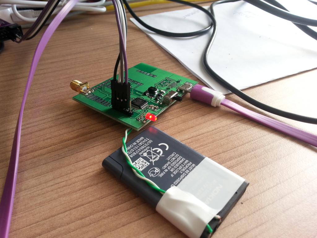
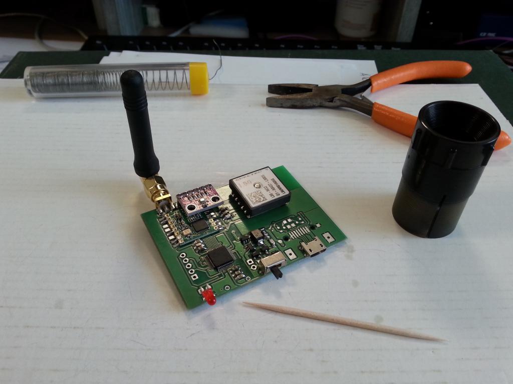
The first attempts to discover range of our box were udertaken during days not feasible for gliding. We’ve placed a tracker on-board of an UL-Fox (that time with it’s engine still working somehow fine) and flew away from the airfield (LKKA OGN receiver) until PK (that’s a friend’s nickname) sitting on the control tower told us over radio we are not on the tracking website anymore. Consequently, we kept flying across various tracks back and there towards the airfield till we finally appeared  on the web again. Hitting the boundary of the signal we’ve somehow established range of less the tracker and more the receiver antennas on the tower. Tough life of the experimenters 🙂

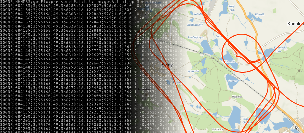
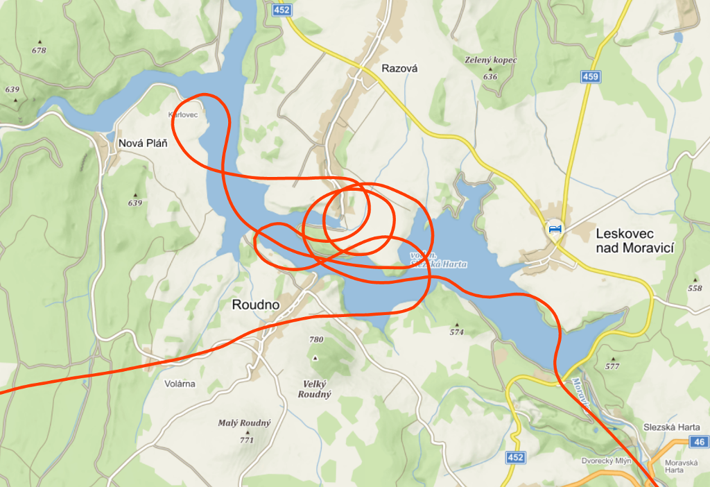
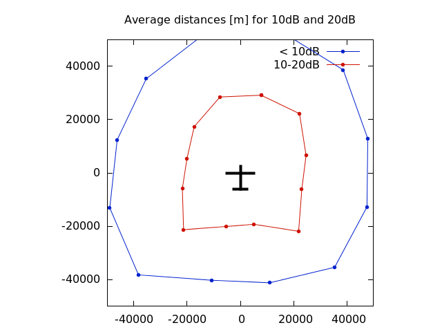
A few months later we’ve encountered the KTRAX Range Analyzer where one can establish the actual range way better and perhaps also more objectively.

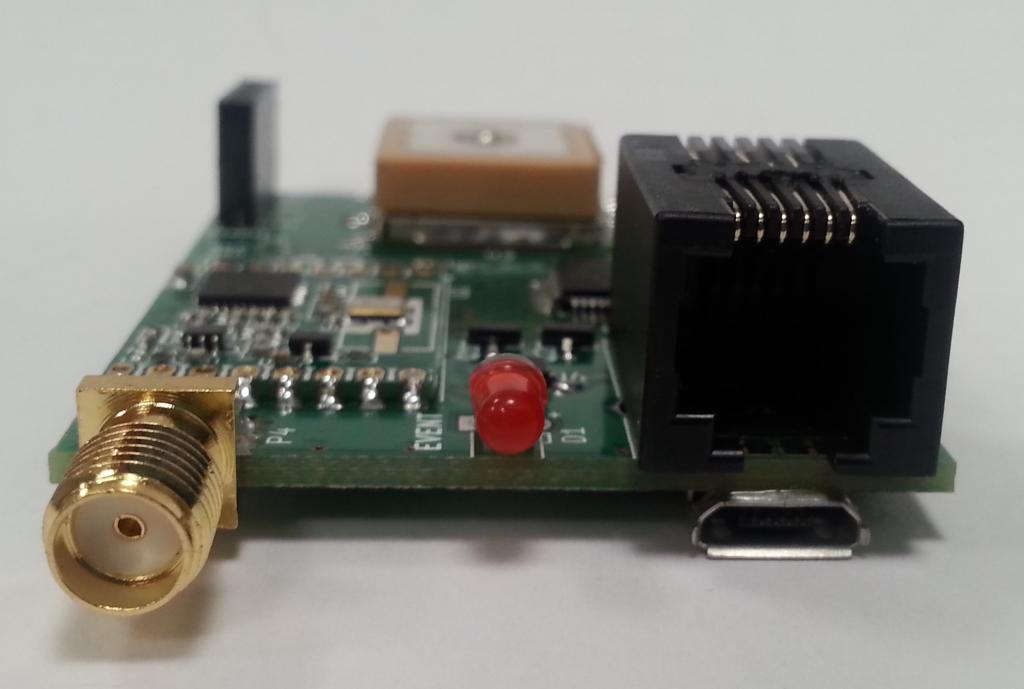
So what is the range if the first experimental tracker built?

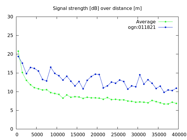
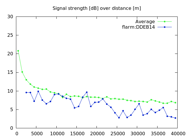
Hell great! 🙂 The signal strength is way high above the average (on the chart above – the green line is average signal strength in the OGN network, the blue one is us!). Of course, it depends also on the receiver location, antenna, LNA or other details. Nonetheless, the KTRAX record is based on a long-term statistics so this effect is hopefully negligible.

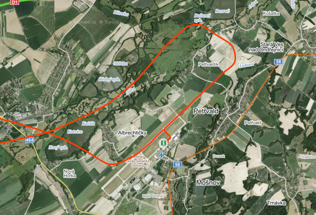
What about FLARMs? It is difficult to asses. I’ve taken 30 randomly chosen IDs and looked on their properties while encountered a lot of differences.

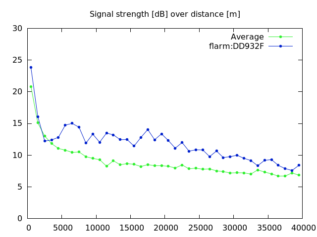
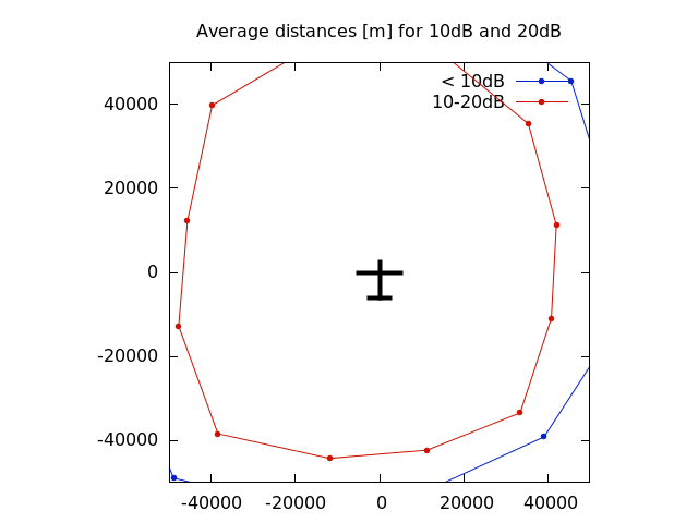
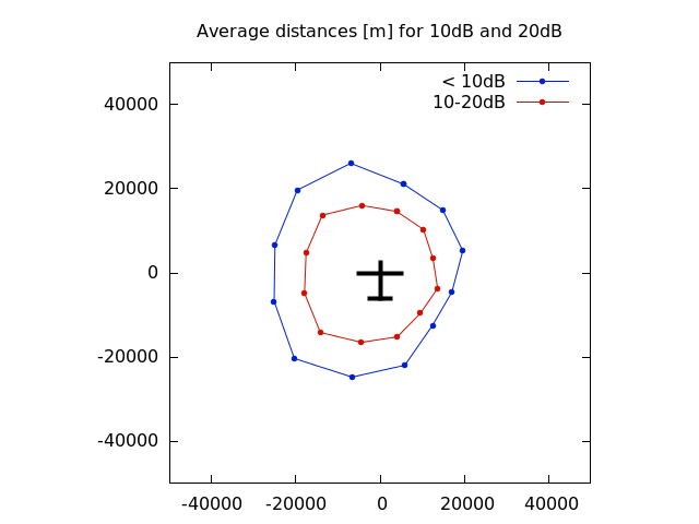
I’ve chosen the DD932F as a typical example but we could easily use also the DD94DD or DD9A1C. In 40km distance only on at the edge of 10dBs.

At this spot I boldly dare to say the FLARM range is a half of our OGN tracker’s range. 🙂 That either means a job well done or I just misinterpreted what the KTRAX stats actually show. Please correct me in the comments if I am wrong.

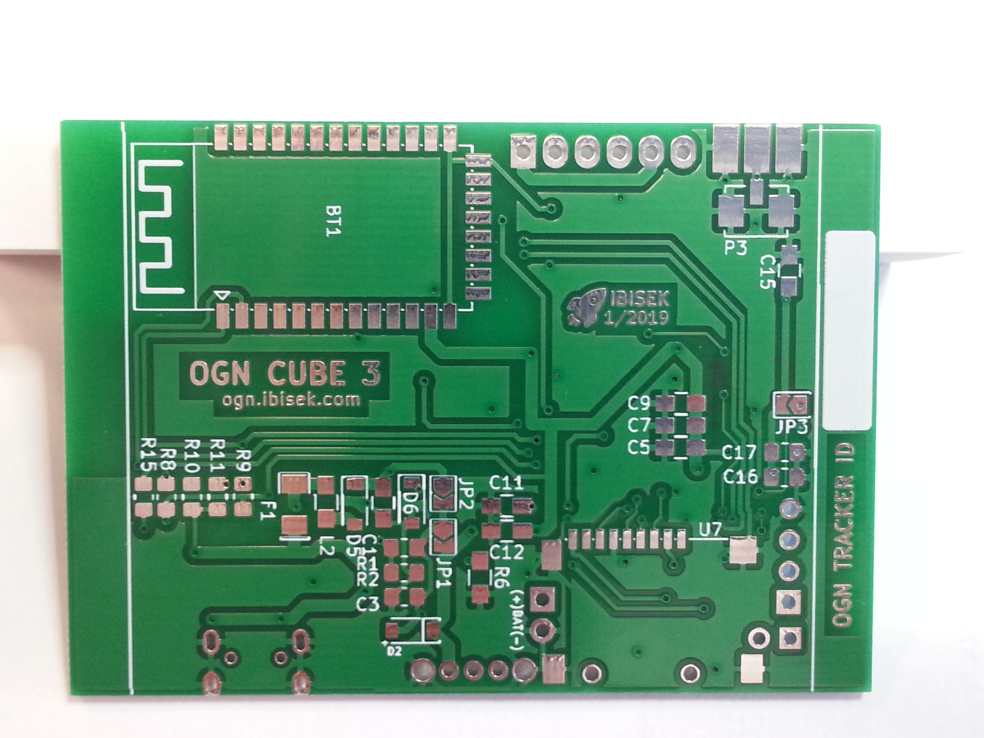
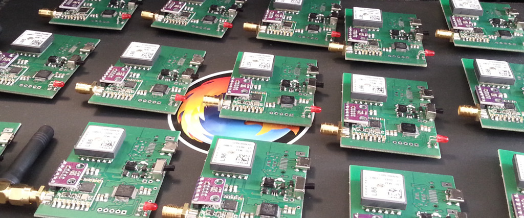
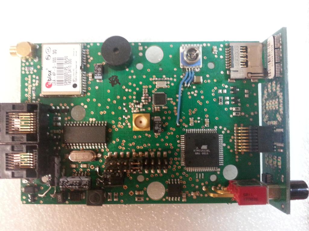
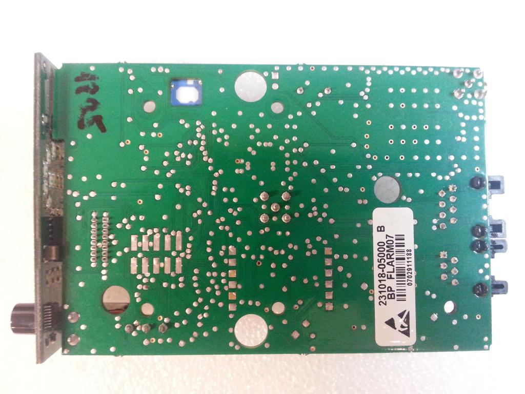
Those who have ever seen the guts of a FLARM box would probably not be so surprised. Antenna in form of an ugly rubber-wire connected to the PCB, which could (does it?) serve as a dirty counter balance (judging by the size of copper fill on the back side of the board). As my education in the field of radio black magic is very limited and the guys and gals from Switzerland have their work very well reqarded I can only assume the know their craft.

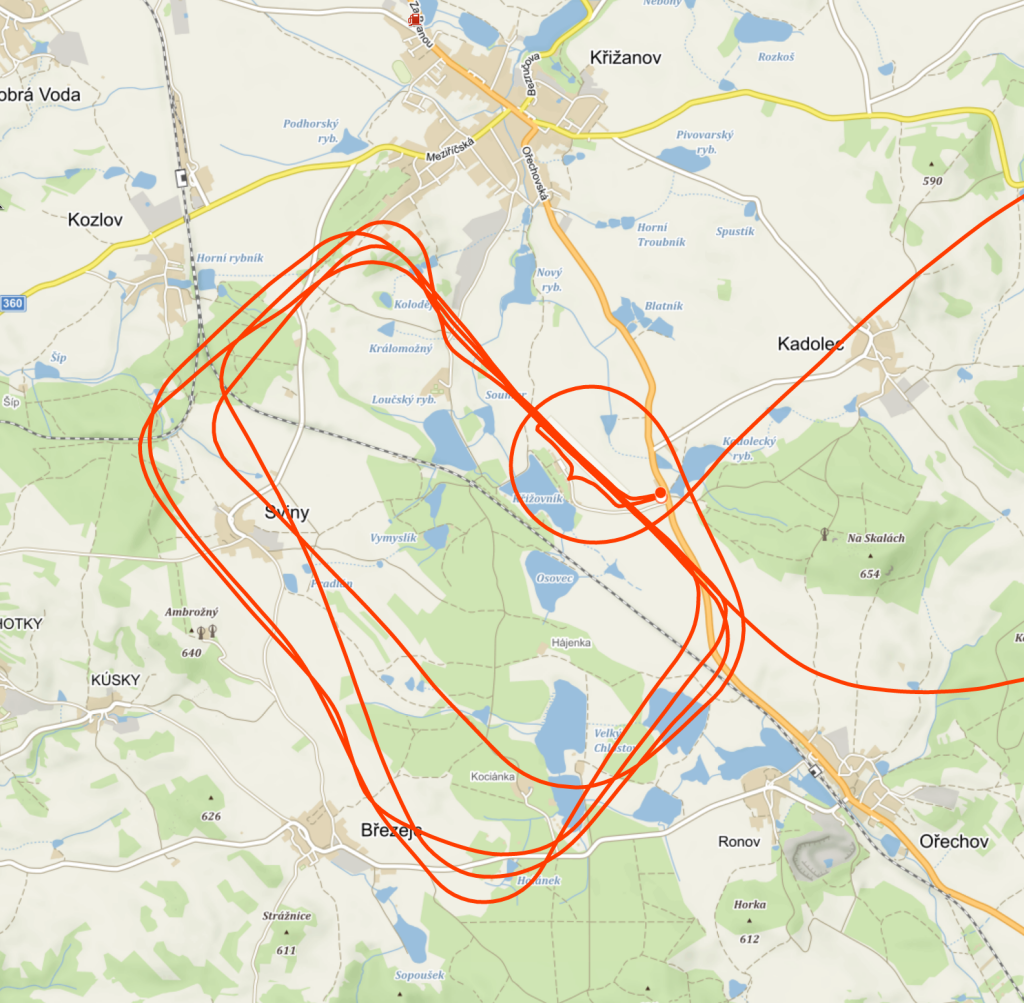
Very important aspect is also the unit’s antenna location. During the competition I’ve seen a FLARM antennas fastened to an iron-beam with a metallic tape or another one hidden under a carbon coaming. And with one contestant even a combination of those above!

Very weak examples can be DDEB14 or DDDDC9 where the signal strength is most likely limited by antenna location and obviously also the pilot him/herself. And there are even a worse examples to be discovered.

If there is enough time I will try to analyse signal strengths from the data acquired during this summer season (I’ve got some 20GBs from 150km around LKKA) and statistically compare the range of FLARMs and various OGN trackers also made by all the folks around. If there were someone who wanted to do such analysis (mainly due to impartiality reasons – don’t trust to stats which you’ve not tampered personally) the data is available upon request ( .. of course to trustworthy individuals only 😉 )

Save

Save