pocitadlo

Competing with OGN Trackers on PMRG2017

With the culminating preparations of regionals in Křižanov someone suggested to build some more trackers for the competition.

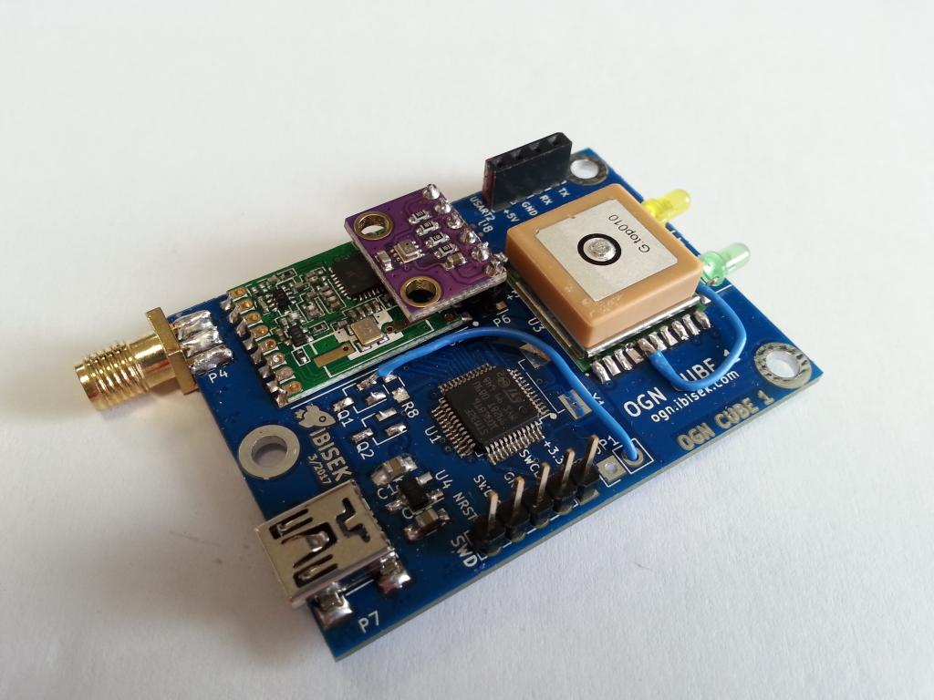
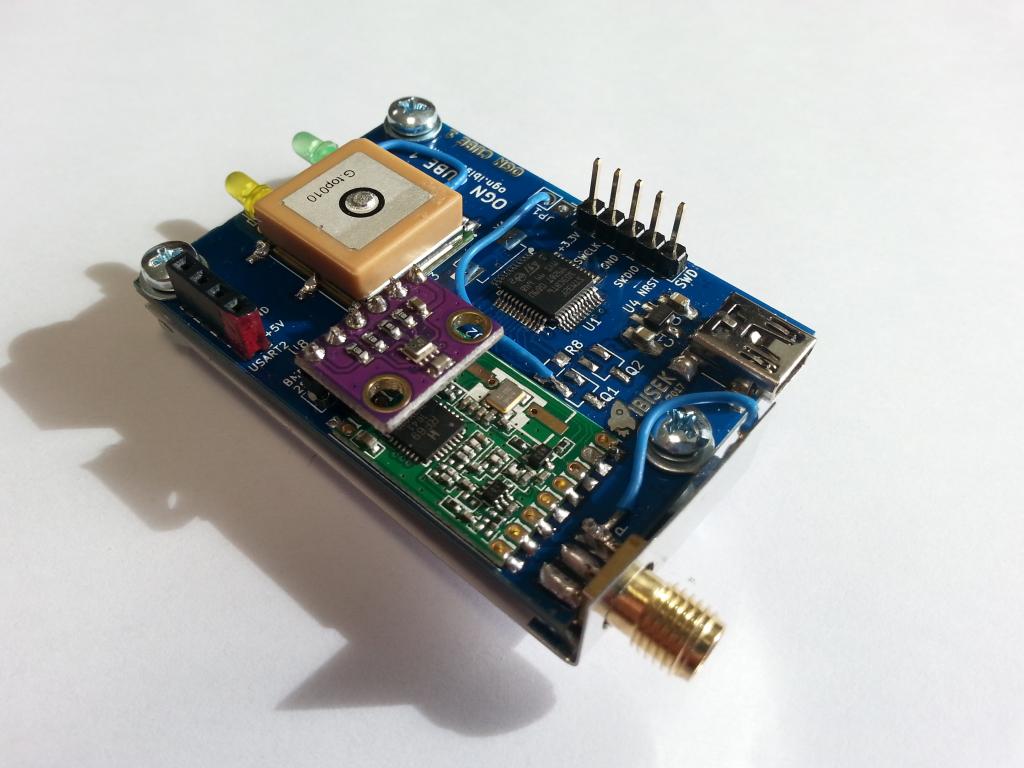
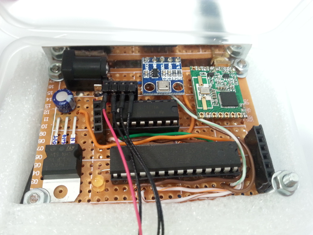
Hence I’ve started to gather all requisites – meaning the parts for the PCB. And yet another trouble was to be encountered. Arrow advertises an “overnight shipping” which was to save my day, however, I did not expect the “overnight” means the package will travel to various locations around the globe every night until it finally arrived to my doorsteps after 20 days of adventurous journey.

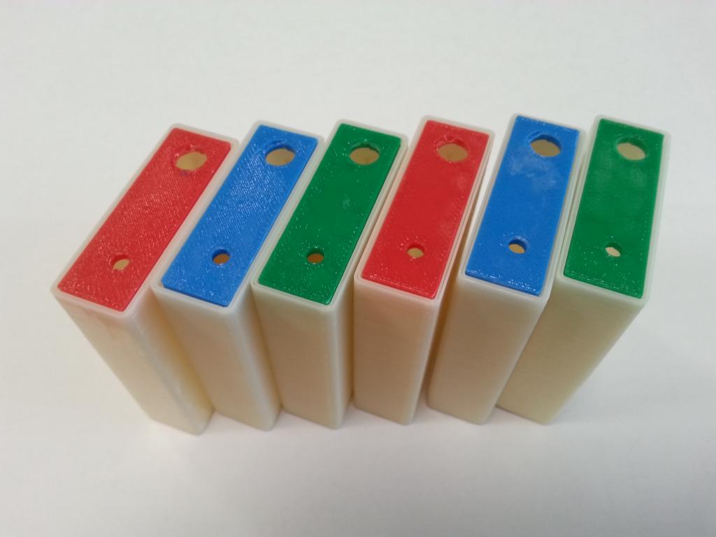
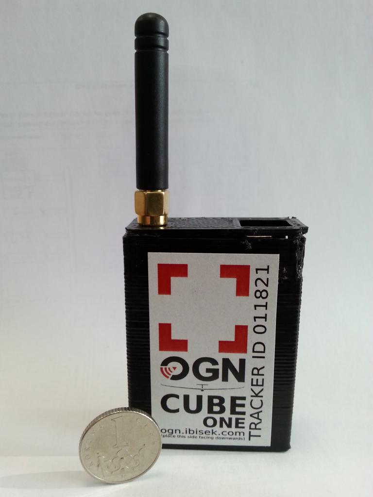
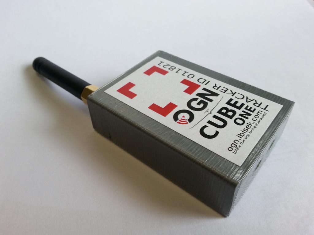
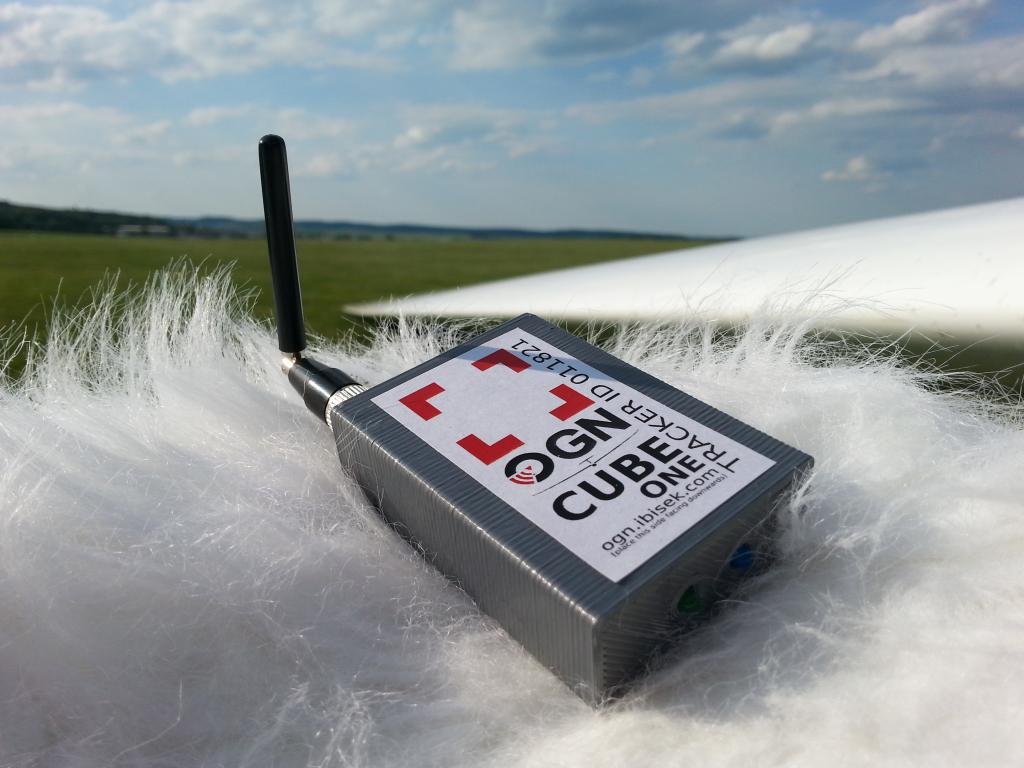
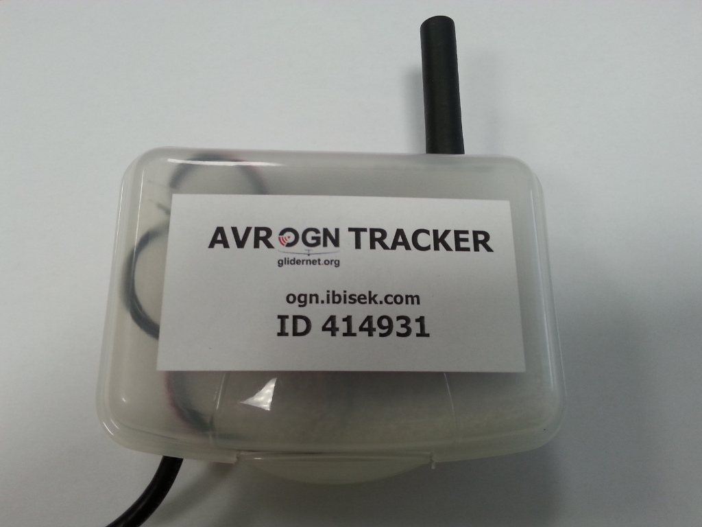
It was a season of vacations meaning Laďa was gone and so his 3D printer. That meant to search for a backup one resulting into use leftovers of various materials of variable qualities and properties. After having printed numerous experimental enclosures the material choice for the competition trackers seem to become a spool of white ABS with lids of multifarious colours.

The source of screws to fix the lid originating from a salvaged microscope camera was already depleted so also the fastening had to be changed. Although a click-mechanism would be better, the lid is now glued in the box with acetone as the printer cannot print  such small details.

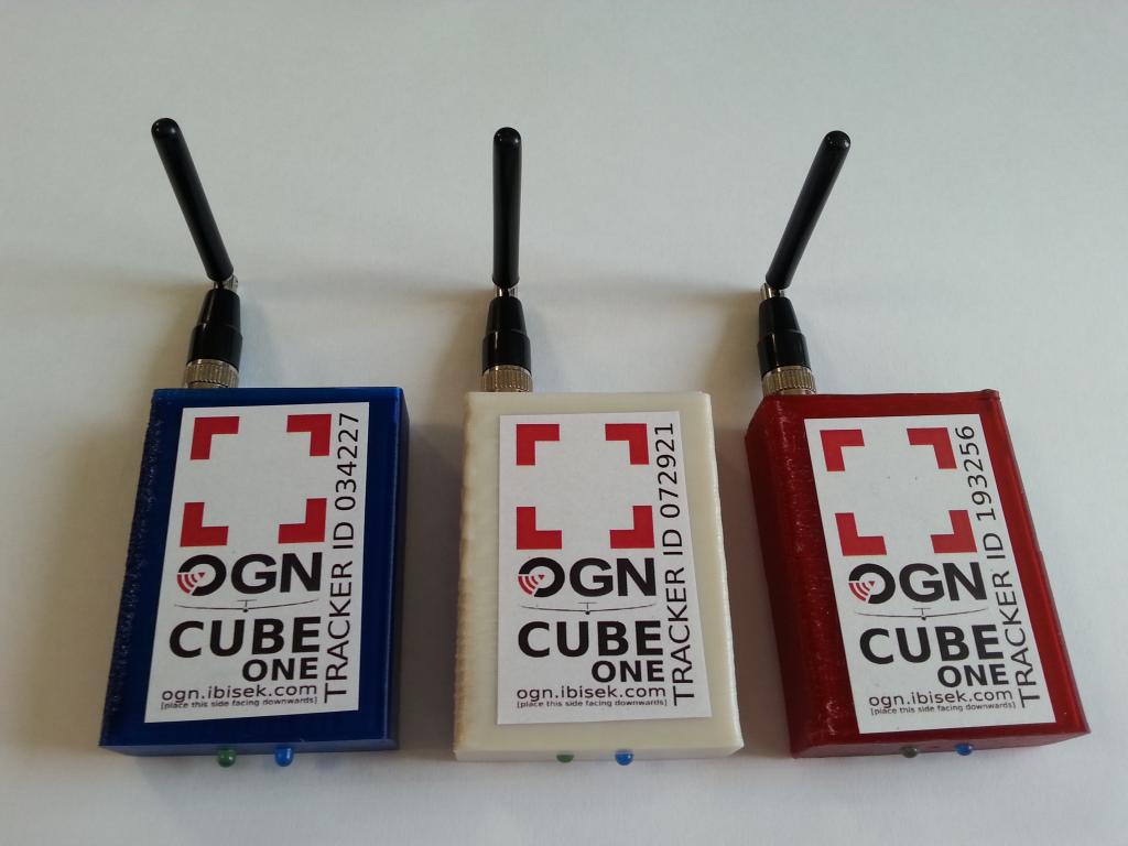
I’ve also experimented with translucent PETG (polyethylene terephthalate glycol-modified). Unfortunately, as it cannot be neither smoothened with acetone nor polished without losing its crisp translucency so the final decision went to snow-white ABS for the boxes and red, green and blue (yes, RGB 🙂 ) ABS for the lids.

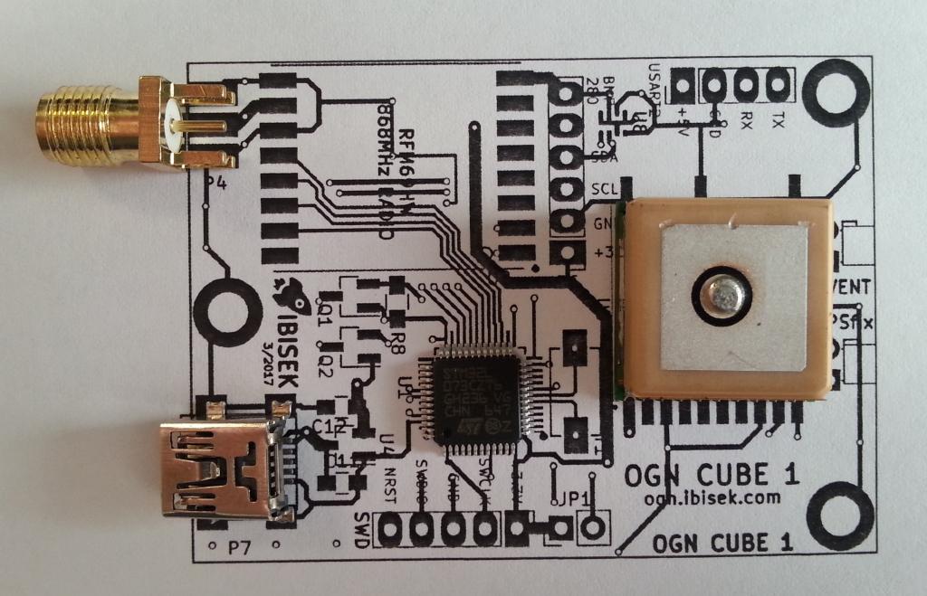
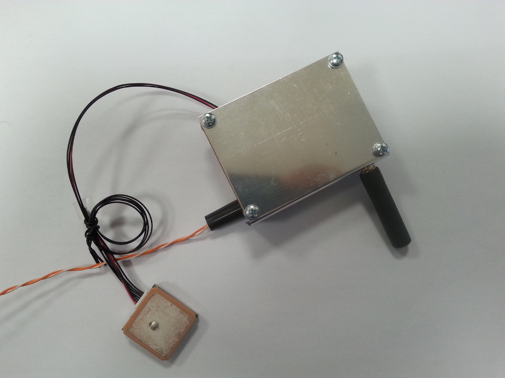
The original mini-usb connector needed to be replaced for a fixed cable as some trackers were losing contact while the connector slid out. On the other hand the power from the USB battery was left as it kept the options open when needed to replace batteries in case discharge of failure.

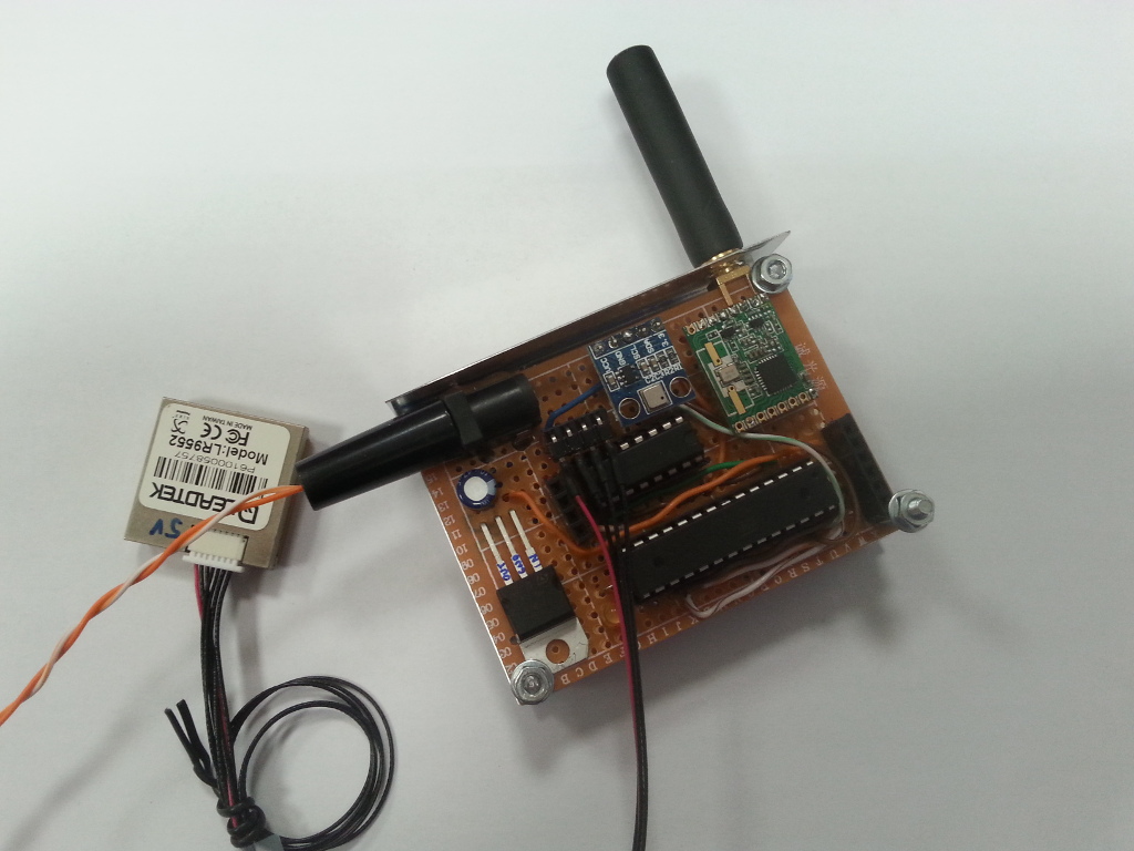
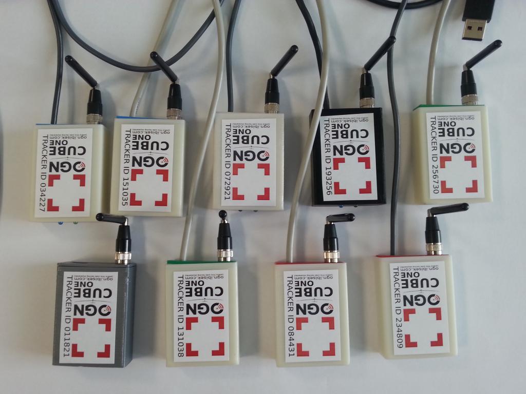
A situation that appeared clumsy at first turned into and advantage. The two thingies – the tracker and the battery – loosely connected with a cable let us to put the battery into a side pocket or anywhere else while the tiny tracker can be placed on top of the stuff piled up in the centroplan to have a clear view for the GPS and OGN antennas while making all the organizers and the contestants happy.

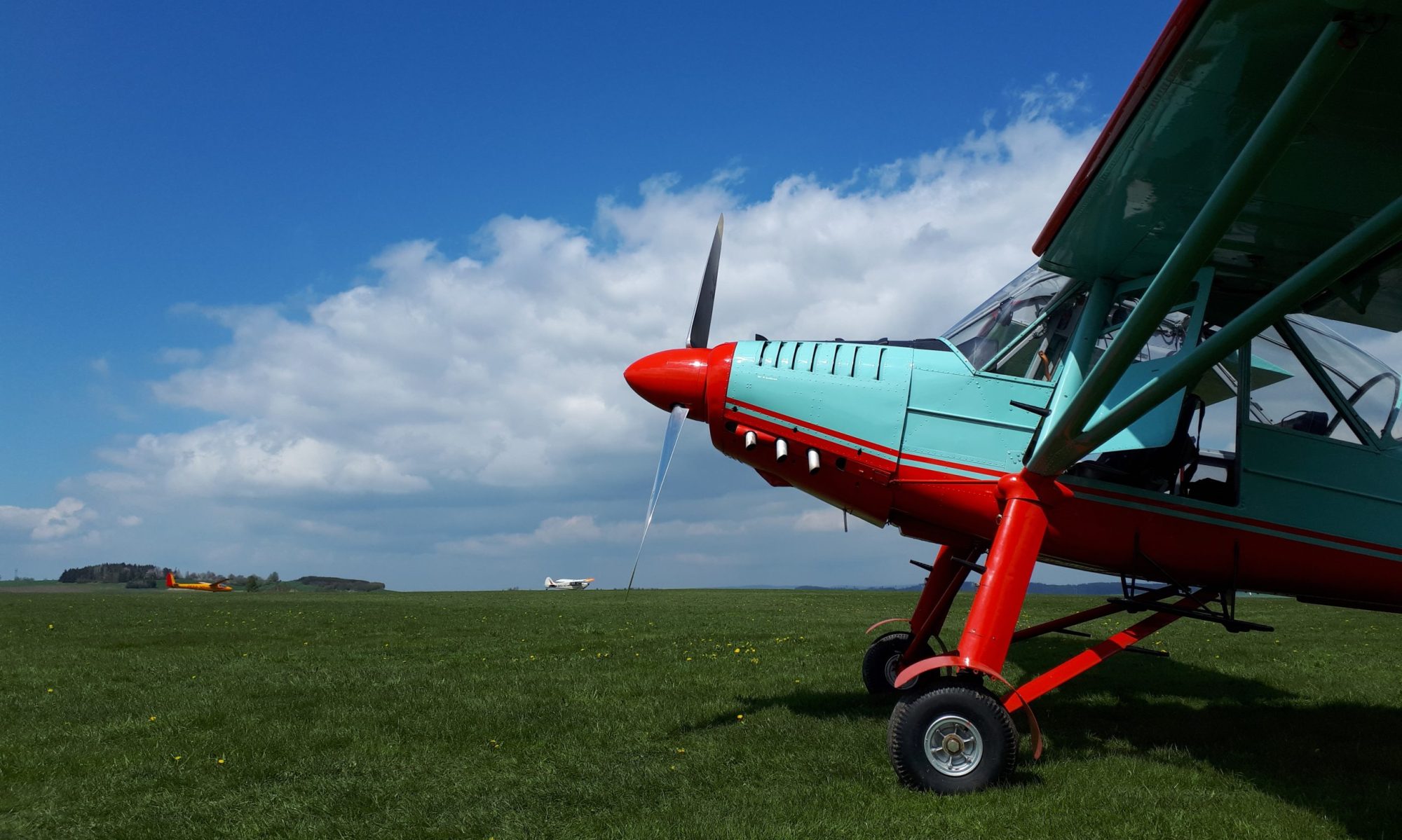
Eight new OGN trackers found its way among the contestants while having served well reliably till the last competition day, last landing and last glass of beer.

Save

Save

First OGN Cube ONE is Out!

April turned to May and the bombastic success was coming – first PCB (of ten) was populated, brought to life and even tested in the air by flying once around the airfield in Fox. The last step in development was closing – what enclosure to use for the tracker? This turned out it should had been the first step of the design..

The mounting holes were originally intended to fix the antenna counterbalance from the bottom side of the PCB. Dimensions of the already existing board do not fit any existing box or the available are  either too hideous (large and just ugly) or incredibly expensive (and still too big; e.g. Fischer elektronik AKG 55 24 xx – I have bought one but it’s not really a fit).

Purely by coincidence a friend of mine -“Glidertools” Laďa – went by saying – “Man, what’s the trouble? I can print you one!”. And thus we started fitting the tracker board into an experimental box made on a 3D printer.

At the beginning it was kinda disaster. We were fiddling with available materials (PLA sucks), ABS, ASA and later we also experimented with PETG. The main goal at that time was to find a way how to separate the antenna counterbalance from the PCB so nothing went off in magic blue smoke. At the same time the box had to be closed for which a printed lid and three screws from salvaged microscope camera served very well. The gray ASA (acrylonitrile styrene acrylate) quickly proved as a well suited material resistant to high temperatures and therefore the first two trackers now fly in this suit.

Another struggle was the OGN antenna. The GPS module with integrated antenna is soldered on the PCB in horizontal position and shall be situated facing the sky, or space respectively. Therefore the box must be oriented the same way (image facing skywards). The radio antenna, on the contrary, is supposed to be vertically polarised – samewise as the receiver’s antennas. That results into requirement of an antenna that could be bent or even better with a joint.

Searching for such one took me almost a year. Again, by a pure coincidence I have found a splendid one when visiting the Ampér 2017 fair, where the exhibitors did not want to understand why I demand an immediate sample and do not want to wait for order from their e-shop to arrive..

Perfect, ain’t it? 🙂

Bugs Crawling Everywhere!

April debugging smoothly transcended to highway to hell. Over the last fortnight trying to find a bug in SPI communication and that bastards is hiding so well that even colleagues MacGyver cooperating with Chuck Norris would be troubled.

All can be blamed to hasty transition from F042 to F103 and to that related change of architecture resulting into libraries refactoring. I’ve already deployed all I’ve got and even borrowed some heavy guns.. and still no idea, nothing changed.

Should start some other business.. beekeeping perhaps?

A (Pre)production Unit

With the end of year 2016 some more folks wanted to have a tracker on board and therefore I started to ponder how to build more units in a nicer or even, let’s say – a professional form.

The amount and complexity of code was growing while not only 8kB nor 32KB FLASH was not enough. 1000 bytes of RAM would be still enough but various almost-undetectable problems started to arise – mainly rare unexpected memory leaks followed by a bit more expected watchdog reboots. It was the highest time to leave the Atmel AVR realm and move to some other, unexplored area where code can be debugged better that by prints into serial terminal.

A new design based on mighty STM32 microcontroller was born. In this case it was the STM32F042 chip – possessing 32 still well-solderable legs, 64kB of FLASH, 32kB RAM, clocked up to 48MHz – a “perfect” embedded supercomputer until the moment 64kB of FLASH was not enough again.

Having spent some considerable amount of time on thinking, searching and comparing various ICs the choice was obvious – STM32L152. It is a low power (good!) microcontroller with 128kB of FLASH, 32kB RAM. Its 48 tiny legs with considerably smaller pitch among them (and that is not so good).

During January a perfect schematic was drawn in Kicad with even better layout. Having double-checked the dimensions of everything at hand I ordered PCB manufacturing and waited. As soon as the boards arrived I’ve started ordering all the parts. This day entered history as Mr. Farnell who claimed to have the L151s readily available for shipment gave me a call that those are not available anymore and asked if I wanted to wait for another 6 months. Luckily are the ST comrades quite smart so the missing hole can be (relatively easily) replaced by the ubiquitous F103.

Physical footprint match is one thing. The architecture is other.  While the F042 is Cortex-M0, the F103 is Cortex-M3 which means all the libraries accessing particular registers need to be again rewritten to reflect all the bloody nuances of that or the other architecture. Shit hit the fan.

Moreover, its March and season is so close..


First Prototype

The first prototype was created in April 2016. Initially based on Atmel’s ATMEGA8 which had to be replaced once the program did not fit its 8kB of FLASH by ATMEGA328 (on which, by the way, the famous Arduino is based). It was time of struggle with timers, SPI and I2C registers that maliciously differ in teeny tiny details.

Two trackers in form of wiring hell and radio modules on long stretching legs can be seen in the front. A quarter-wave antenna on the top, an almost half-wave counterbalance became one of the legs. One of the trackers still based on M8, the other already running on M328. A bit chaotic setup, but the end justifies the means, right?

And because everything worked as intended it was the right moment to put it all together and up in the skies!

Powering the box from USB cable was the best initial idea (which actually proved to work very well). Later on all other components were completely replaced (besides the radio module). Starting with GPS module with antenna borrowed from local bakery owner, pressure sensor from an experimental variometer, perfboard made of paper, all inside a soap box.  It was a great prototype which served perfectly and reliably.

Now, under the cumulus clouds, gray shit or in clear blue skies can be seen with the “PK” livery 🙂