pocitadlo

Antennas, Antennas, Antenas!

This write-up was supposed to come in February 2020 but some other, “more important causes” made me to reschedule a bit, well for almost a year. In late autumn 2019 I asked a friend with not only access to spectrum analyser but primarily with knowledge and expertise of using it to measure properties of five various antennas I acquired during that year mainly for experimental purposes. I have been carrying the charts presented below in my backpack for most of this time and now it is finally a good moment to share those measurement results with you.

Antenna #1

This is the first and initial antenna which has been used with the CUBE ONE trackers. It took me some time to find a perfect match which would fit behind the canopy without drilling a hole into the hood. I had discovered this one on the Ampér 2018 eletronics fair that used to take place every April in the Brno exhibition centre. For long time I was not certain what the company name was. I just found out it was Sectron and the antenna type was AO-AGSM-TG09.
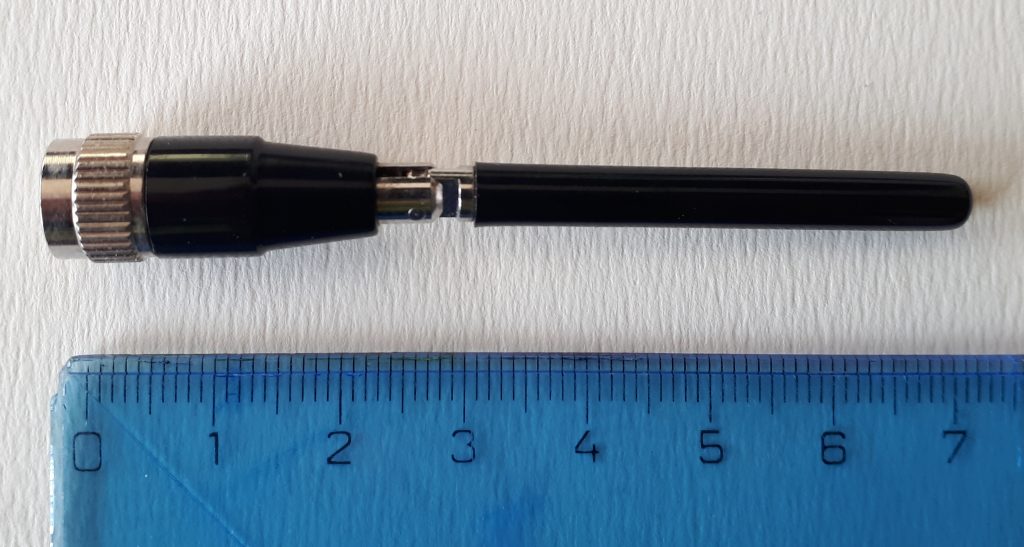
Antenna #1: used to fly (and still does) with the CUBE ONE trackers.

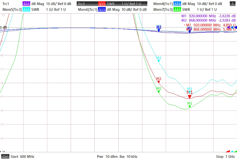
It was love at the first sight! Tiny dimensions, SMA connector, specifically designed for the 868MHz band and the ability to bend which made it so perfect. It works considerably well with metallic counterpoise which in CUBE ONE was located inside the box right under the PCB. Surprisingly, it performs rather well in air-to-ground traffic, despite the measurement result. Well, see for your self:
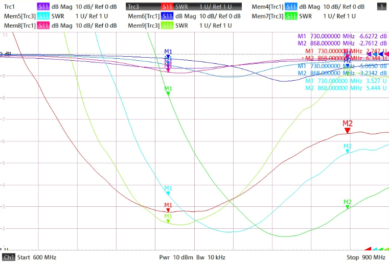
Properties of antenna #1

The M1 marker is around 730MHz while the frequency band we require (868MHz) is way out of the valley – find the M2 markers on the right. Also its configuration has a huge impact on its performance – the RED line is when the antenna is straight, light-blue when bent in 90 degrees and the bottom green one depicts its properties with a screwdriver in hand touching the outer SMA connector’s ring and making it almost well tuned. Nice but obviously for children to play as commented by Zdenek.

Antenna #2

Why and how did I find this gemstone? Mainly because the CUBE TWO needed one and as I might have mentioned earlier I had just a fuzzy idea what company I purchased the first ones. It took some time but after endless nights spent with comparing and contrasting various types, sizes, brands and even colours I discovered the 2J010 from SOS Electronic .. which seems to be also out of stock at this moment .. 🙁
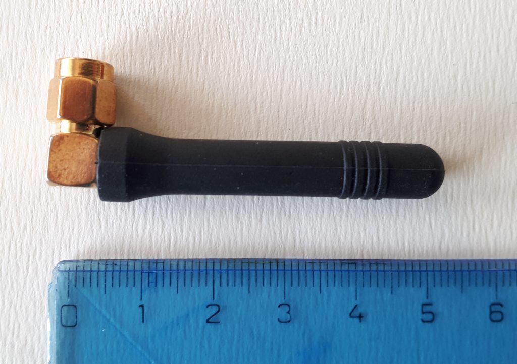
Antenna #2: currently used with all CUBEs TWO and THREE.

This story is still at its very beginning and I am already going to spoil the drama – this antenna performs the best from all here presented ones. It performs very nicely at 868MHz – see the markers M2 and M3 (-16dB or -23dB respectively). The M1 is set at 903 MHz. The bottom green line is again with a screwdriver touching the antenna and its influence is negligible. This antenna has the really best adjustment. It allows you to see other gliders at distance 5-7km all around you (well, this number hugely depends on mutual attitude and position of the gliders, of course).
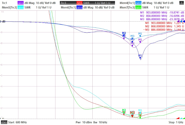
Properties of antenna #2

Antenna #3

Another specimen with a bendable joint. It looks like a wifi-piece but is not. Its performance is low. Attaching a screwdriver to the ground had not much of effect but significant at the joint. Even worse properties were observed when a hand was in close proximity to the antenna – rendering it rather useless. Next!
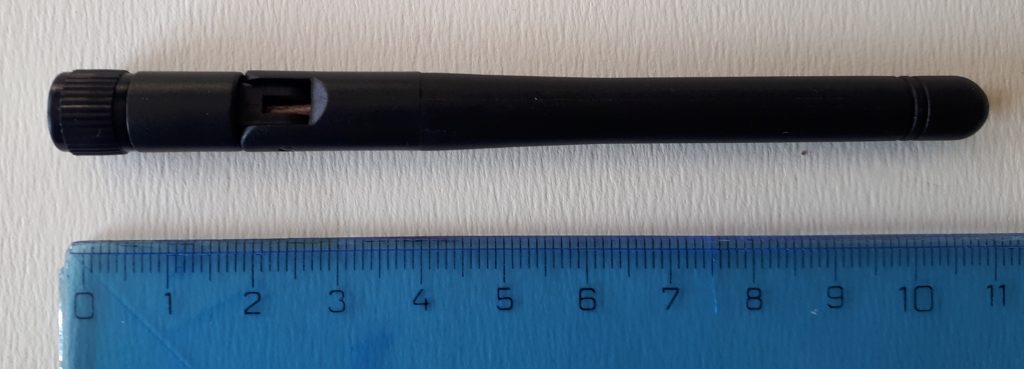
Antenna #3: useless
Properties of antenna #3

Antenna #4

My personal favourite. It allowed the longest air-to-air distance I have encountered during the last gliding season – 23km! And that is only the farthest glider I have noticed in a moment of playing with the LK8000. And there might have been even longer distances! (it could be a good idea to add this information to the flight record..) Furthermore, it seems to to receive reliably other gliders at distance of 5-10km which makes it better even than the antenna #2. However, it is a bit bulky and kinda pain to fit it inside the tight cabin of LS-1. But with LS-8 it won’t be better 😉
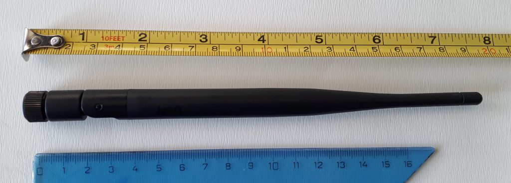
Antenna #4: currently mounted and flown in AF 🙂

Screwdriver in vicinity it had no influence whatsoever. Not even a hand around its root and all around the body. Its adjustment to the 868 MHz band is a bit worse but it has certainly better gain than #2. Marker M2 at 868 and M1 at 920 MHz.
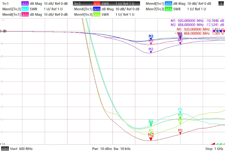
Properties of antenna #4

Similarly to #3, the #4 has has been sourced from China which makes it with a nicer price tag (but who knows what will happen with shipping and taxes in 2021?) but with the sour uncertainty of repeatability of such purchase. Some other pieces I had bought were completely out of specs and violent manual adjustments had to be performed before throwing them to the garbage bin. This buy might have been pure luck but also a good source of nice antennas! Who knows? But I love it! 🙂

Antenna #5

I spotted similar kind of antenna at the T-Cup 2019 in Káďa’s Cirrus. It seemed to be a good idea to use one (or two sector) antennas to scan the airspace in front of you with higher precision – not only to detect possible incursions but also to spot other contestant’s thermalling on the track before you. Her antenna was apparently custom-build piece of PCB (I had a photo.. somewhere) and I also wanted to explore this area a bit. For that reason I decided to obtain a completely different antena ‘architecture’ including a 2m long cable.
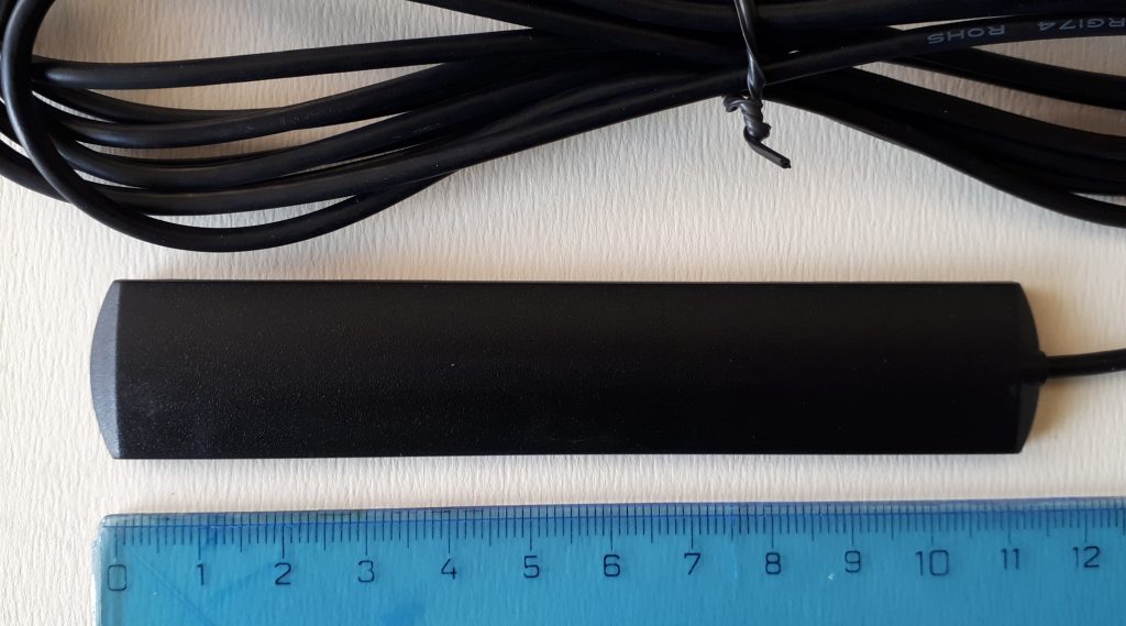
Antenna #5

The measurement has shown it is adapted somewhere for the 900 MHz band. The cable, however, influences its properties significantly and even more do the dimensions and material of the body it is located on. Dead end.
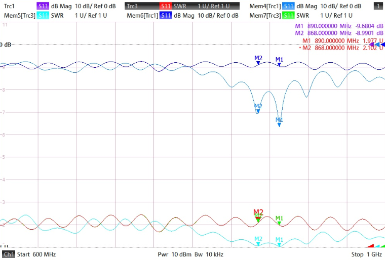
Properties of antenna #5

Summary

The antenna #2 seems to have the best adjustment for the band we need for our OGN adventures while the #4 seems the provide the best air-to-air range. Both of them can provide pretty decent service in terms of range and reliability of data reception. Hence both of them shall and will be considered for the upcoming seasons 🙂 As the #2 is not available at this moment I might try to buy more samples of #4 and check if all of them have the same or similar properties like the single sample I have at hand. Still, buying stuff from China is a tricky business. Either way I will certainly share the outcomes once available! 🙂


Lessons Learned During ognLogbook Development

As I mentioned earlier, what was supposed to be a one-weekend project has turned into four-months-long fine tuning effort and even now in November still not in excellent shape. In this post I would like to share the lows and highs which one can encounter when writing such on the first sight simple and straightforward application – the ognLogbook.

The first instances false take-off and landing detections were spotted when exercising spins and winch-launches at the LKKO airfield. Detection routines based mainly on ground speed (GS), initial thresholds values and minimal time of flight of 2 minutes (one cannot do a circle faster, right?) were failing when GS sunk down close to 0 km/h after a winch-based take-off, kept at 0 thru the climb and continued right above minimal GS limit during the circle. To make things even more tough those guys and gals also trained emergency landings across the runway making duration of one ‘circle’ flight just around 60 seconds.

Later that week I have noticed the second type of detection problem – GS close to 0 during spins with Blanik somewhere around LKVM. If you do more than one spin it already takes some time which had been evaluated as landing with conseqeunt immediate take-off. This trouble originated mainly from the vaguely defined touch-and-go detection routine.

What the heck is going on?

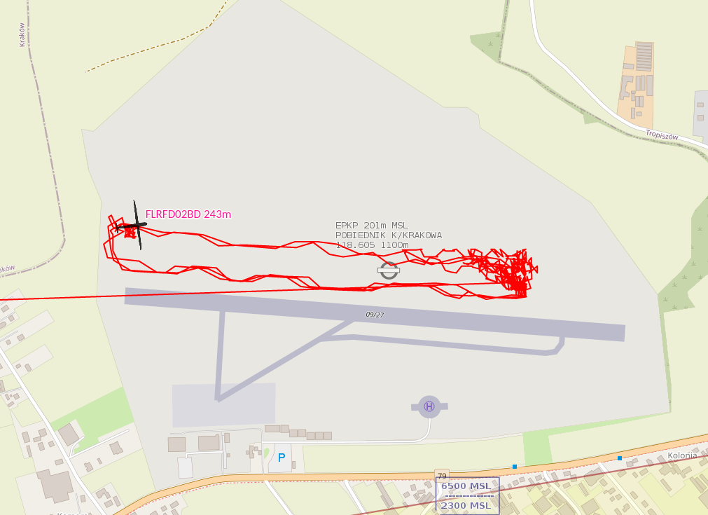
Another madness had been detected at Krakowski Aeroklub in Poland as shown on the picture above. My hypothesis is they were testing their engine after an overhaul by taking off and landing immediately while still on the runway. The time, speed and altitude difference conditions were met and thus this was also detected as a (short) flight.

And there is even more crazy stories like that! 🙂

Ongoing detection problems made me to consider spawning yet another functionality – calculated flight altitude above ground level (AGL). This became quite tricky as all the available code examples did not work for me (a common situation), hence a bit hacking had to be used. You can get the EU terrain elevation data freely from the ESA’s Copernicus sattelite with 20m horizontal resolution (nice) in tile-files of total size around 20GiB. These had to be resized to tiles 500x500m to reduce its size to some 8MiB. Why? The initial workaround could be seen in calling a command line utility (gdallocationinfo) for every position (well, not every, just those near take-off and landing) by specifying latitude & longitude and parsing resulting output from the proceses’ output stream. This meant to load the (joined) tile-file from the hard-drive (SSD became a life-saver!) into memory every time the script was called and waiting for the process to finish. You can imagine the overhead! A month later I discovered the gdal binary version needs to fit exactly the python library (you need to downgrade in the system) and this enabled every received location’s altitude to be resolved from a more precise (200x200m) file of current size of 160MiB in real-time! Here is still one drawback, however: The elevation data covers only the territory of the European Union. The rest of the world is just dragons..

The most recent problems have arisen recently with the autumn wave season: The winds at FL195 blew so strongly the gliders came to have a negative GS! (greetings and congrats again to Hedlanda aeroclub at ESNC in Sweden! 🙂 ). This made the AGL calculation an indispensable step for every received position from the OGN network.

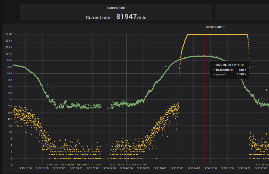
The initial ognLogbook‘s coverage was mere 300 kilometers around LKKA. Early on I started receiving inquiries if the area can be extended to cover this and that airfield so it has risen up to 1000 km with the center still at our hangar mainly due to the server performance issues. At that time the logbook was deployed on ‘CML6’, a machine based on remainder of an broken laptop with the Intel Core i7-3537U CPU @ 2.00GHz. This CPU hit its limit during a sweet summer day when the entire Europe went bananas and every available glider was pulled out of the hangars with a dream of at least 1000-kilometer-long flight 🙂 The last recorded beacon rate was 120000/min. The task queues were configured with ceiling of 1M (a million) records and the records that not fit into were brutally dropped.

Processing limit was hit hard on beautiful summer day.

But still this wasn’t really the biggest issue. The caches could have been configured as virtually limitless (well, only by total 8GB of RAM) and no data was dropped. Just then the data processing of such extent has taken until early morning hours .. two days later.

It was obvious that the 4 cores of the CPU (two physical) were not enough for five processing threads of the logbook application ( 1 – data ingestion, parsing and sorting, 2 – OGN beacon processor, 3 – FLARM beacon processor, 4 – ICAO beacon processor, 5 – maria db insertion queue and 6 – influx db insertion queue). The last one was only possible after migration to more powerful virtual server sporting four physical Intel Xeon Silver 4214 @2.20GHz cores allocated to just to our gorgeous ‘CML7’.

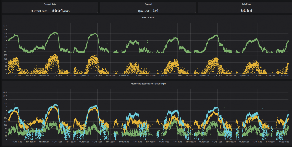
Late autumn data traffic in the OGN network. In the upper chart the green dots indicate number of incoming beacons and the orange shows total number of tasks waiting in the queues. The lower chart shows traffic by tracker type – blue are Flarms, orange ICAO and green OGN trackers. Note the Y-axes are logarithmic.

As long as the generously provided virtual machine is running we have a stable hive to process and further tinker with our OGN data. Currently, the entire flight record of every detected flying craft is stored into the influx for more detailed processing. Nonetheless, not for eternity – the retention period is configured for 7 days and then the data is discarded. The main reason is the tremendous amount of data: approximately 800 million records per week were stored at the and of August 2020.

There is still a lot of work that could be done – both in the realm of the data processing algorithms and also in the web interface (e.g. responsiveness, live data feed and more). Or rewriting into rust? If you were willing to pass a helping hand or can’t stand some issues you can see, you are warmly welcomed to contribute to the GitHub repository https://github.com/ibisek/ognLogbook. Any enhancements will surely be appreciated by everyone! 🙂

OGN Logbook

In the meantime while endlessly waiting for CUBE 3.1’s parts to arrive I got teased into coding (yet another) logbook engine / web page as the other ones have supposedly some nuances missing. Flying is still off-topic as the monsoon weather keeps us on the bar at best. Hence on one rainy weekend I convinced myself I am capable of doing such thing while it shouldn’t take longer than one or two days.. right?

Well, yes and no. It was really functional that Sunday evening but numerous tiny details had to be polished over the following month. At this moment it seems to be quite functional (I admit there are some unwanted “features”) and stable. Therefore, it is my pleasure and privilege to present you the ni­gel­na­gel­neues OGN Logbook! 🙂

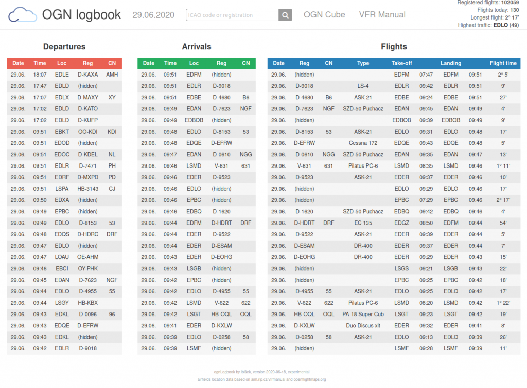
OGN Logbook - main page

The home page shows current traffic as observed by the logbook backend. There are some differences based on you browser’s language settings. German speaking users will see ED, LO and LS traffic by default, Czechs and Slovaks airfields with ICAO code starting with LK and LZ and finally all others can see the entire world’s traffic.

By clicking onto an ICAO code you are forwarded to records related to the airfield of your choice. A click on an airplane’s registration shows you detailed information about selected airplane. Except the main page all presented flight records are listed by selected date, which you can change using the small arrows in the header.

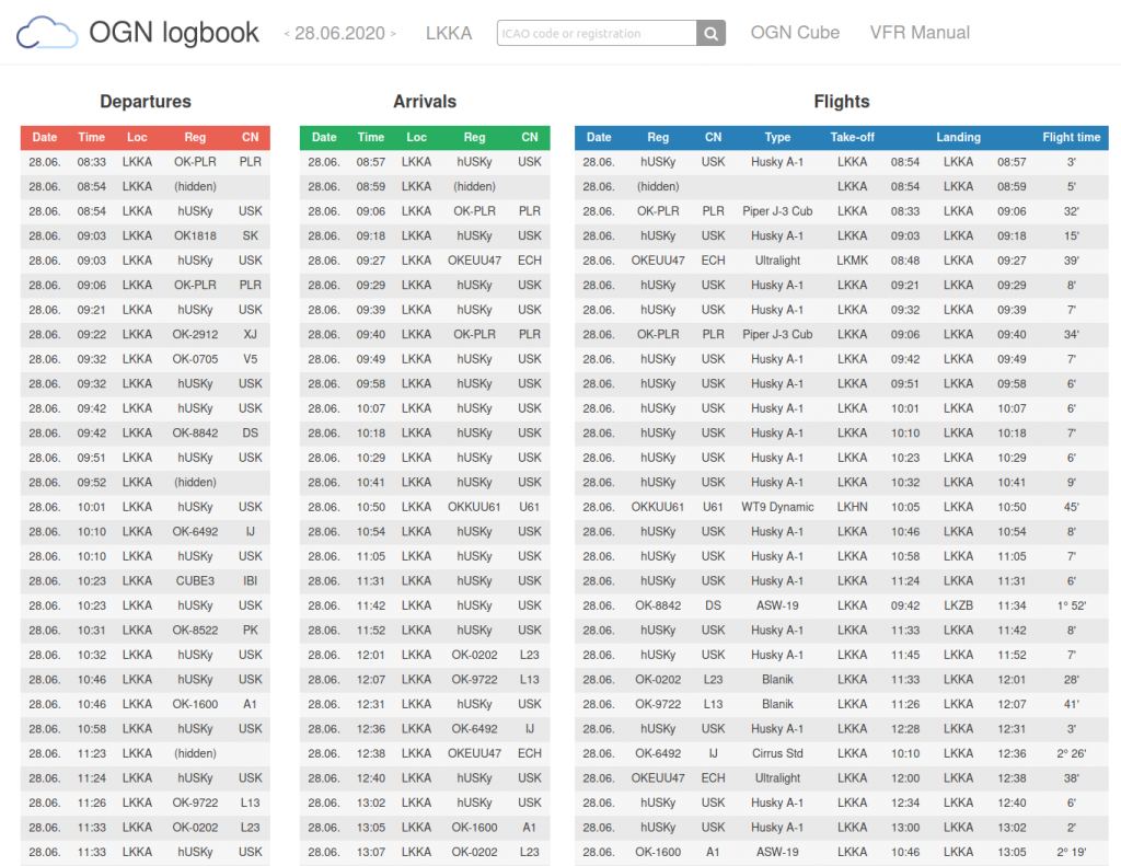
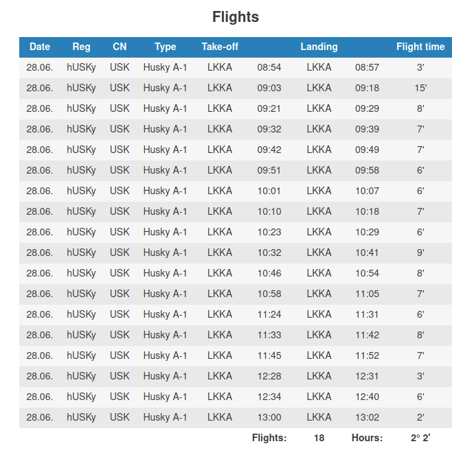
Sometimes the calculated flight times may seem to be wrong. For example in the image above there is a flight which took-off at 09:51, landed at 09:58, showing 6 minutes of flight while based purely on this presentation it should clearly be 7 minutes. The matter (and trouble?) is the presented timestamps are rounded to nearest minute while the flight time is calculated from flight duration recorded in seconds and even then rounded – which makes this flight time information more precise. But it looks wrong. How to round minutes and calculate the times is still a subject to wild discussions.

As mentioned earlier, the logbook observes and records all traffic in the OGN network. However, only take-offs and landings in vicinity up to 4 km around air-fields and ports are taken into consideration and stored into database. The landables list is based on czech VFR Manual and entries sourced from openflightmaps.org. No field-landings (so far). All vehicle take-off velocity is set to 50 km/h and landing to 20km/h for gliders and 50 km/h for tow planes. For landings there is yet another condition applied – of being below altitude of 160m above terrain level.

A useful feature is .csv export of the airfield’s traffic of the selected day by clicking on the ICAO code while on the airfield’s detail page. The file’s structure is specific for Air Jihlava’s Flight Office. This import is now being integrated into the FO suite so one can import the data by just a single click. The files are also easily accessible by using the download url directly (and amending the date if required) by your scripts. If another format would be useful for you, please let me know!

Convergence Prediction

This fancy title hides the magic of future track calculation and possible collision prediction followed by reasonable warnings. Reasonable in this case should express no crazy alerts while thermalling with twenty other gliders or in situations like following a tow plane on a fifty-meter-long rope. How is it done? Witchcraft!!

We can work with the information available at each moment coming right out of the thin air. The OGN trackers can and eagerly do receive transmissions from other units in reception range. By sorting and ordering these beacons we could (re)construct trajectory of each particular airborne “target” and in theory predict its future behaviour by employing sophisticated mathematical models. A little concern comes with complexity of such methods and the requirement of real-time availability of such results while all computations need to be performed on a fairly limited tracker’s brains. Hence, some simplifications had to be made..

Let’s start from a single point – the most recent beacon received. Such packet of data contains identification of the other airborne vehicle, its speed, altitude, heading, climb/sink rate and angular velocity. From this single point we can iteratively estimate future discrete locations with certain precision. In case of having two (or even more) consecutive locations received from a single transmitter, the accuracy of this method can rise significantly. Between two known states of the other object we can also include speed changes (i.e. acceleration or deceleration), angular velocity and altitude deltas into the calculation. However, the more distant future we look into the more imprecise this prediction will become. This is not a crystal ball, but it works fairly well.

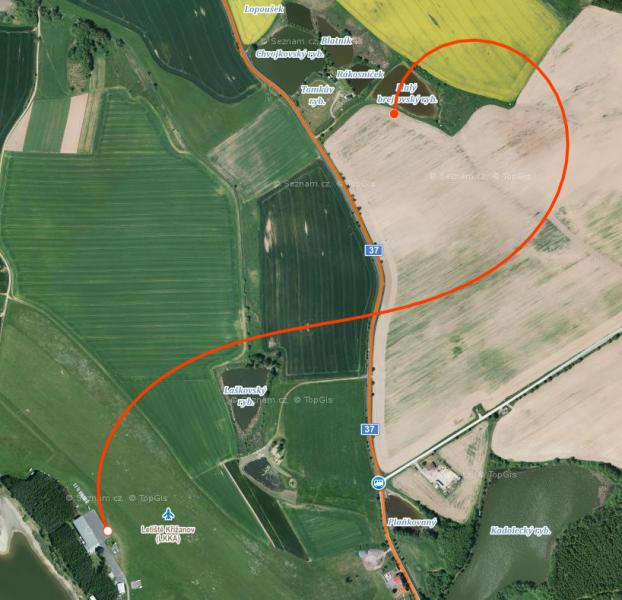
Track estimation of a plane flying northwards above hangar roof, maintaining constant speed, heading and angular velocity.

Exactly the same track prediction can be done based on our most recent location(s) and flight directions. After combining all track-points by calculating distances along corresponding (time-wise) pairs while incorporating headings, climb/sink rates and angular velocities we can issue informative warnings to the acting pilot in charge. And that is the theory of this operation.

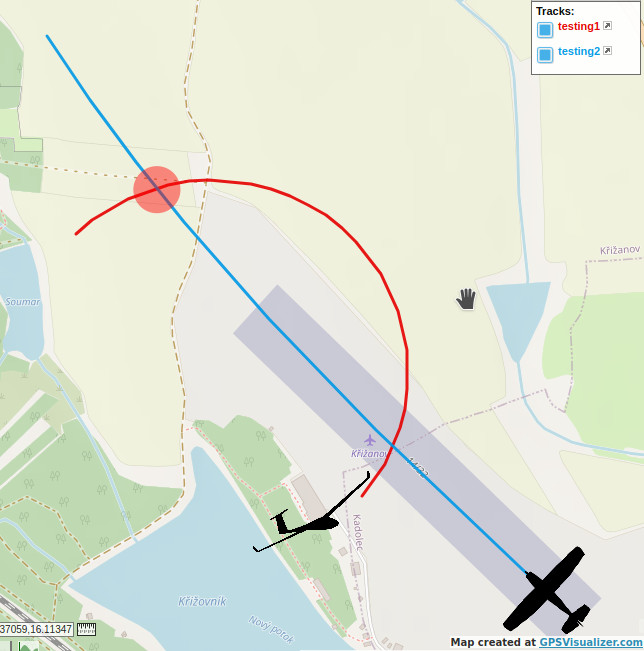
Situation of a glider at low pass while another plane taking off. From the gliderpilot’s perspective there is plenty of room while the dangerous area is at the second track-crossing where the other plane has already gained some altitude and speed.

Now it’s time to put these hypotheses under real-world flight testing! If you don’t hear from me anymore all this was obviously wrong 😉

Running OGN Receiver in Balena.io Node?

Manual maintenance could be a lot of hassle especially when one keeps multiple OGN receivers running. You need to update one thing on the first location. Then you decide to do something similar on the second while the third one wants to be kept up to date too. You really don’t want tame differently configured receivers anyway. Later on, when everything is nicely set up and in sync a friend wants to receive a local weather station or something completely else..

Just a few days ago I hit in my podcast listening queue to a CZPodcast‘s (Czech only) an episode about something called balena.io. As I am skipping the tracks in the queue randomly and I’ve already noticed this balena-thingy to be mentioned a couple of times, it became obvious I have to give it a try. Not only by listening that particular episode but also by installing it on my (surprisingly supported) Raspberry Pi of the very first generation!

It all starts with creating an account (eh, another password to remember) on balena.io website. I was pleased those guys support so many devices, even my Pi 1. To install the “balena os” you need to pre-configure an image that you then just download and flash on the SD card. An old two-gig card was just fine and I was running a Balena node in (almost) few steps (well, this tutorial looks lengthy but is is not that bad, really).

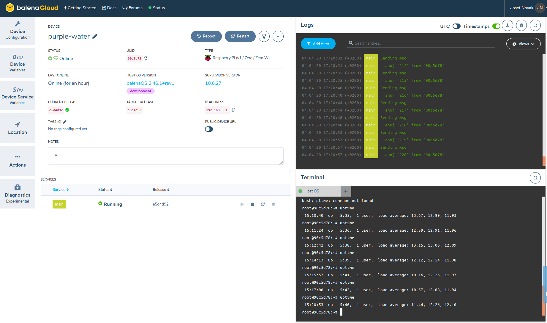
Now: what about the app? Before installing the OGN receiver binaries I’ve decided to run a simple script that would send just some messages across the net just to have a starting point for a more complicated setup. The experimental script was really simple:

#!/bin/bash
id=`hostname`

mqHost=$MQ_HOST
mqPort=$MQ_PORT
mqUser=$MQ_USER
mqPassword=$MQ_PASSWORD

i=0
while true
do
    ((i++))
    msg="ahoj '$i' from '$id'"
    echo "Sending msg"
    echo "  $msg"
    mosquitto_pub -h $mqHost -p $mqPort -u $mqUser -P $mqPassword -t testing/pi1 -m "$msg"
    sleep 4
done

Creating a Dockerfile based on the example was a bit trickier. The documentation describes there can be multiple dockerfiles and the order in which they are processed. There is also something called Dockerfile.template which ought to help you with multi-architecture setups and some other matters. And here was the spot I hit a wall. The example Dockerfile.template did not work due to the first line “FROM balenalib/%%BALENA_MACHINE_NAME%%-node:10-stretch-run” – on git push the hook on the server complained something about uppercase letters in this line. Googling it was helpful only to that extent that there shall be another – dockerfile.template (with lowercase D!). Solved by creating a symlink. However, the git hook complained the ‘Dockerfile’ is missing (had to make a copy of Dockerfile.template; yet another symlink didn’ help). And the initial image had to be changed. The resulting Dockerfile/Dockerfile.template/dockerfile.template is then as follows:

#FROM balenalib/%%BALENA_MACHINE_NAME%%-node:10-stretch-run
FROM balenalib/rpi-debian:stretch-run

RUN apt-get update
RUN apt-get install mosquitto-clients -y

RUN mkdir -p /opt/app
WORKDIR /opt/app

COPY testScript.sh .

ENTRYPOINT ["/opt/app/testScript.sh"]

Concequently, by calling git commit & git push the image gets build on the balena cloud server and after seeing blue unicorn you know it got through successfully. In the project dashboard you can observe the docker-image update progress on all your devices (you can have as many as the free quota (10) or your wallet allows).

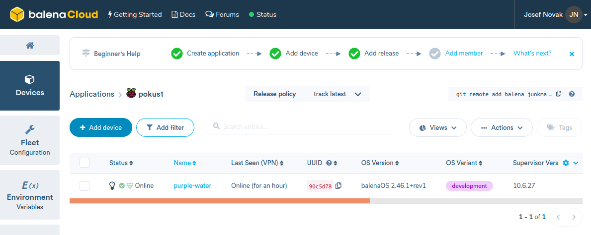
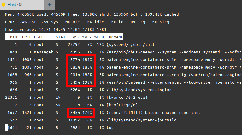
So far so good. A neat great on the device detail page is you can seamlessly connect straight to the shell and also into a running docker image (or images if there are more of them). But wait – what is that device load? 18? I understand it is only Pi 1 but..!? The ACT LED on the board indicates there is no disk IO (which is a good sign – the card is old, slow and I don’t want it to die by wear too early). It could be caused by the docker image update process. The Pi is connected to the Balena cloud servers through a VPN and the update itself could be a bit demanding. Lets wait for some time for things to settle down..

After an hour the load was still around 12. I guess the 256MB of RAM is just too little. The Compute Module 1 has double of that and it may do the difference. This is a dead end for my Pi 1 in combination with Balena. Our most powerful receiver runs on quad-core Pi 3 is currently down and I will have to climb the hangar roof anyway – will try that ONE very soon!

OGN Cube Control Is Out!

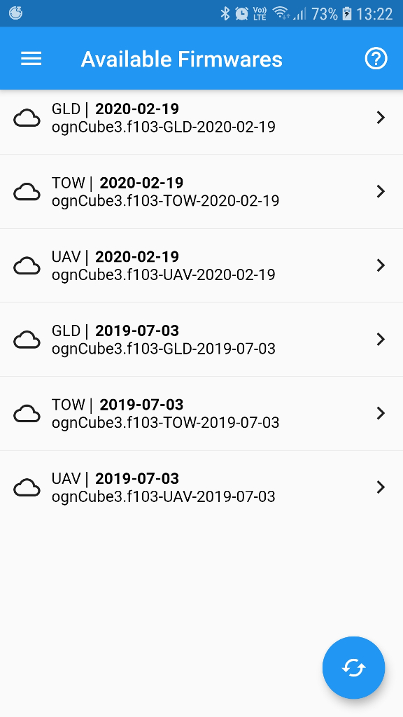
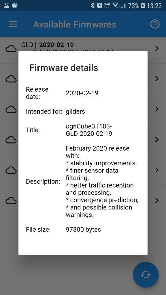
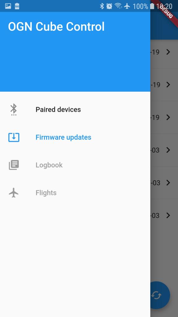
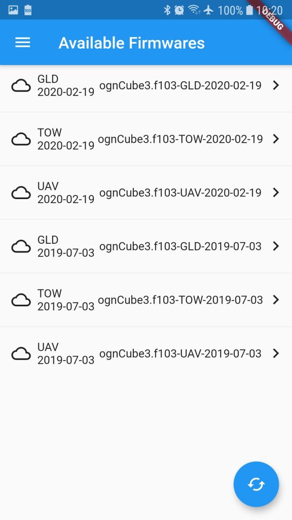
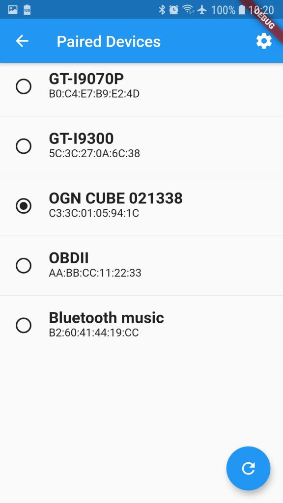
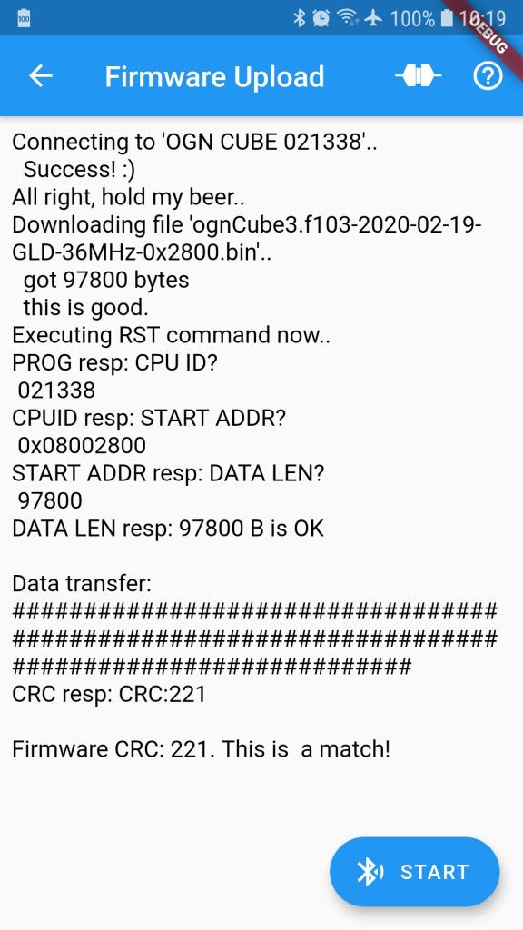
It did not take that long to push the application to the Android Play store (thank you, Petr!) and hence I can proudly announce the OGN Cube Control app is now available for download!

Presently you need to be online to fetch the firmwares while they are not stored anywhere in the phone. Though, offline storage for people without a data plan (like me) is considerably high on the todo list.

OGN Cube Control

The dry February in conjunction with forthcoming season kicked me out of winter dormancy and resulted into unexpected programming hyperactivity. The idea, or rather necessity of an application which could update firmware in the Cubes outside my lair wirelessly and seamlessly was forcing its way for quite long time.

I had already started with its development the previous spring based on my somewhat limited experience gained from programming the Outlanded and VFR Manual apps some years ago. However, this has been disrupted after several weeks due to hitting a dead end. Some communication problems with bluetooth devices originating from my probably deep misunderstanding of the Java-based Android API made me to suspend the app development indefinitely . Approximately six months later I circumstantially participated on Brmo conference where some weirdly-looking and talking chap was demonstrating cross-platform mobile development based on Flutter and Dart. It looked kinda neat, straightforward, simply made a very positive impression on me. All right, I really loved it! But another four months have passed till the day when I finally convinced myself into FINALLY MAKING IT! And that day has happened to be circa 96 hours ago..

I have spent 14 straight hours on Saturday, 12 on Sunday (I seriously needed to eat something), 4 hours on Monday night and 4 more today morning and now can boldly announce that it WORKS like a charm! 🙂

It still needs some polishing but we already plan to publish it it into the Play store very soon so you guys and gals can upgrade your lovely little trackers to the most recent firmware there is! 🙂 The other features like logbook or flights overview will come out a bit later.

Big Trouble with LittleFs

Full track recording is one of the nice-to-have functionalities of the CUBEs. The problem here, however, is that the SD card which is used to keep the data gets easily damaged as data flushes to the FAT filesystem cause considerably high wear, especially in the file allocation table (file size & last modification time). The latter could be avoided by disabling the last file updates time in code. Still, the file size and number of sectors allocated is updated every time a block is added to the file. Keeping the data in memory and flushing in larger chunks may seem to be obvious solution, but when taking the MCU’s RAM size of 20kB (while a lot is already allocated) and FAT sector size of 512B into consideration, one can see there is not much maneuvering space.

Hence, the LittleFS seemed to be the perfect solution. Power resilience and wear leveling make it an exact fit for this troubles until you realize its code base is over 4000 lines and make it considerably spacious after compilation – 8KB, even when forcing size optimisation and omitting unused routines in the compiler settings.

In combination with the pending problem of the rest of my code being already a tight fit into the F103CB’s 128kB FLASH (there is also a custom 8kB bluetooth boot loader for firmware updates), the size of resulting binary with LittleFS included has reached the point it does not fit into the program memory space.

Well, what now? There are two options. The first one is to use an F103 MCU with more FLASH like the STM32F103RB. The catch here, are its 64 pins on the larger footprint while the current PCBs is layed-out only for 48 pins of the CB variant. And as I don’t really want to be redesigning the PCB at this moment another option seem to be quite feasible – to replace the MCU with another one. The nice thing with STM’s controllers is they tend to have compatible pinouts. And as I already have some supply of STM32F030CCs in my drawer (and have big plans with that one in another project), this one seem to be the right fit for replacement. It’s got 256kB of FLASH and 32kB of RAM (comparing to 20kB of the F103CB). Some of the libraries I use will have to be extended to support the F030’s architecture (ARM Cortex M0 vs. M3, the buses and peripherals are organised in a bit different manner) but it would keep the footprint small while opening the opportunities for further development! 🙂

But as things never can go easy, there is another problem. In the recent months the Standard Periperal Libraries (SPL) are for some reason not available for download for the System Workbench for STM32 (sw4stm32) and I cannot make it work even when downloaded them manually from the STM’s web. I have reported the problem on the openstm32.org forum already in two posts (the first, the second) with no success so far. Even the SPL firmware for the F103 doesn’t work now for me.

(Edit) I’ve eventually found a workaround. It’s crude, but it does the job! 🙂

(Edit2) Here you can find backup of all STM32 firmwares that were still available from the stm32targets.xml file.

CUBE3s Available for Ordering

Few weeks ago I had silently added the Choose & Buy option in the menu above but somehow forgot to announce that aloud. I have just noticed mu last post is from April and since that time this site looks kinda dead. But I am telling you – it is NOT! 🙂

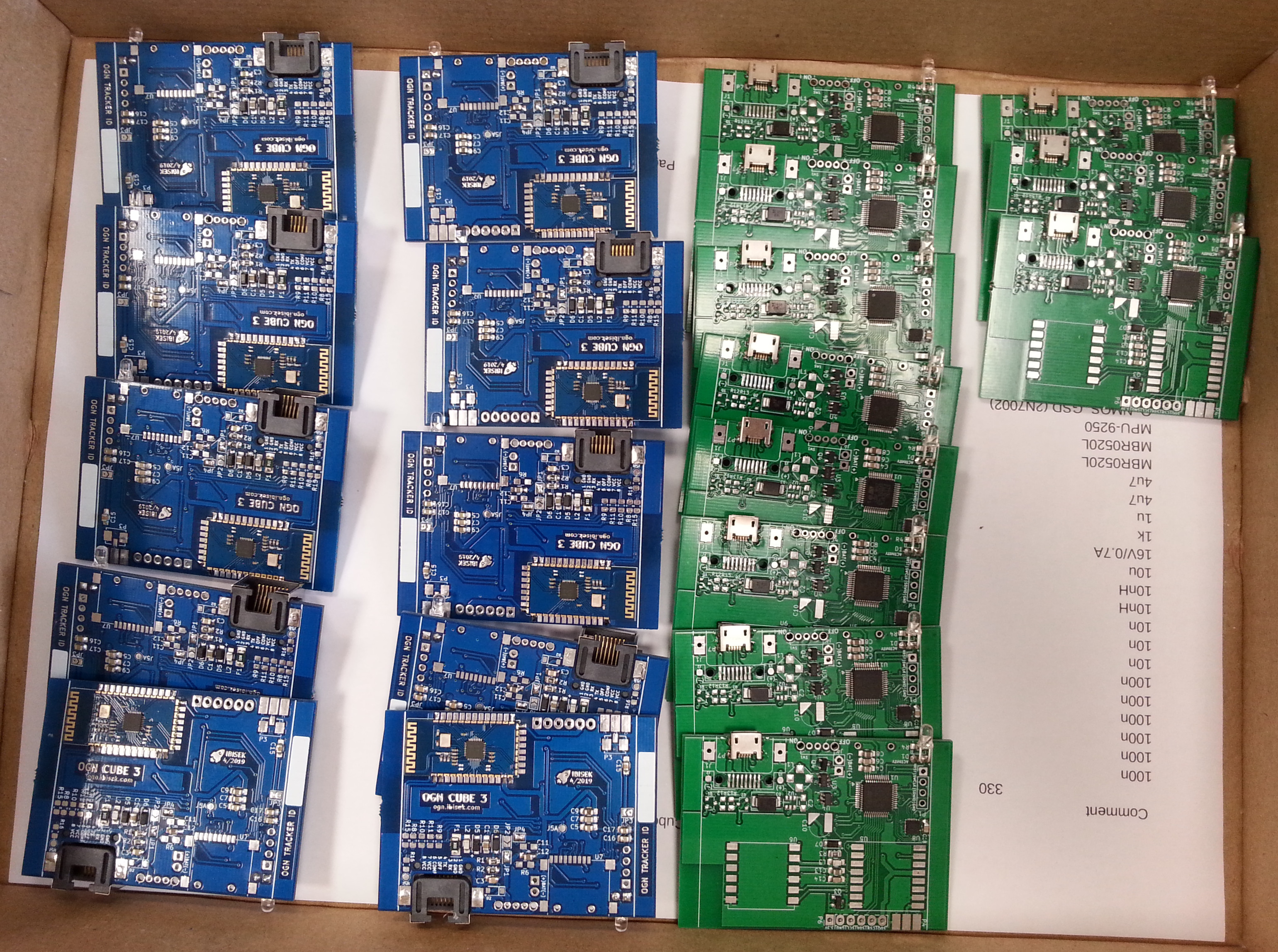
We have made twenty five more Cubes (yes another 25!) and those are now being shipped around the world! I wanted to speed up the production process a bit, hence this batch is partially machine-populated. This helped significantly but not as much as I hoped – mainly due to my mistrust and doubts – which were, again, completely unnecessary as it turned out in the lucky end.

I plan to write a longer post about this endeavor later on – a story about going to small production without any prior experience. Yet, the season is on, let’s do some soaring first! 🙂

A LOT of Cubes

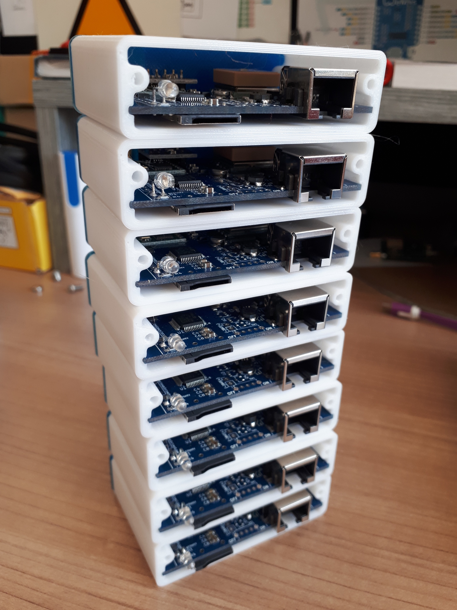
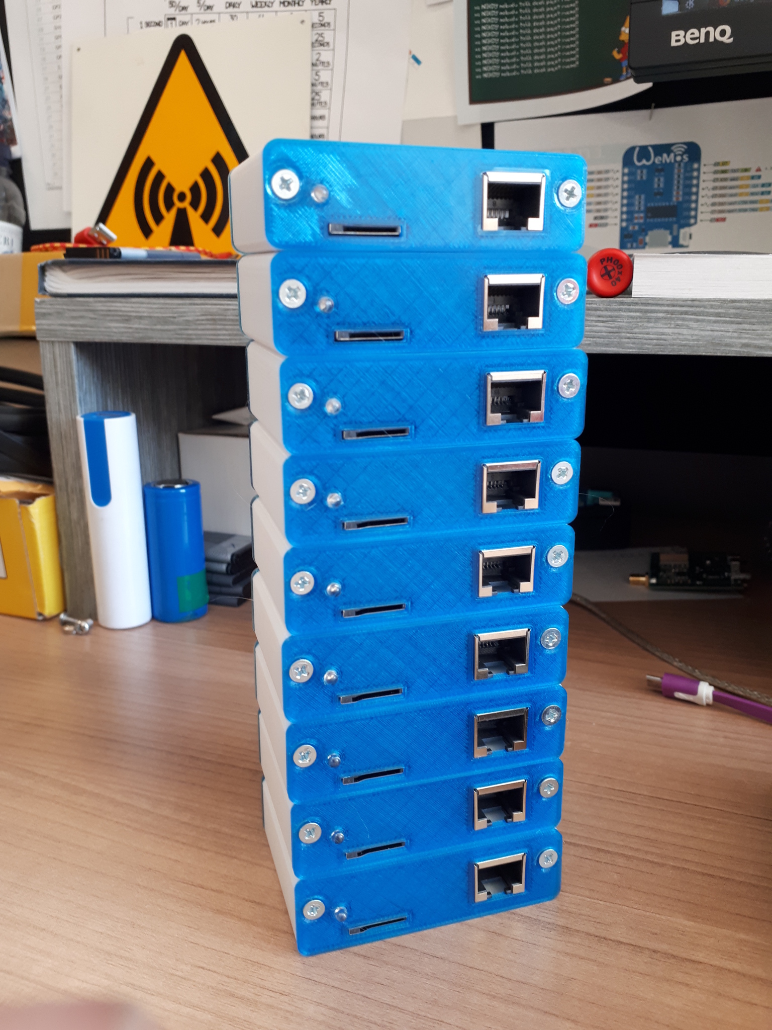
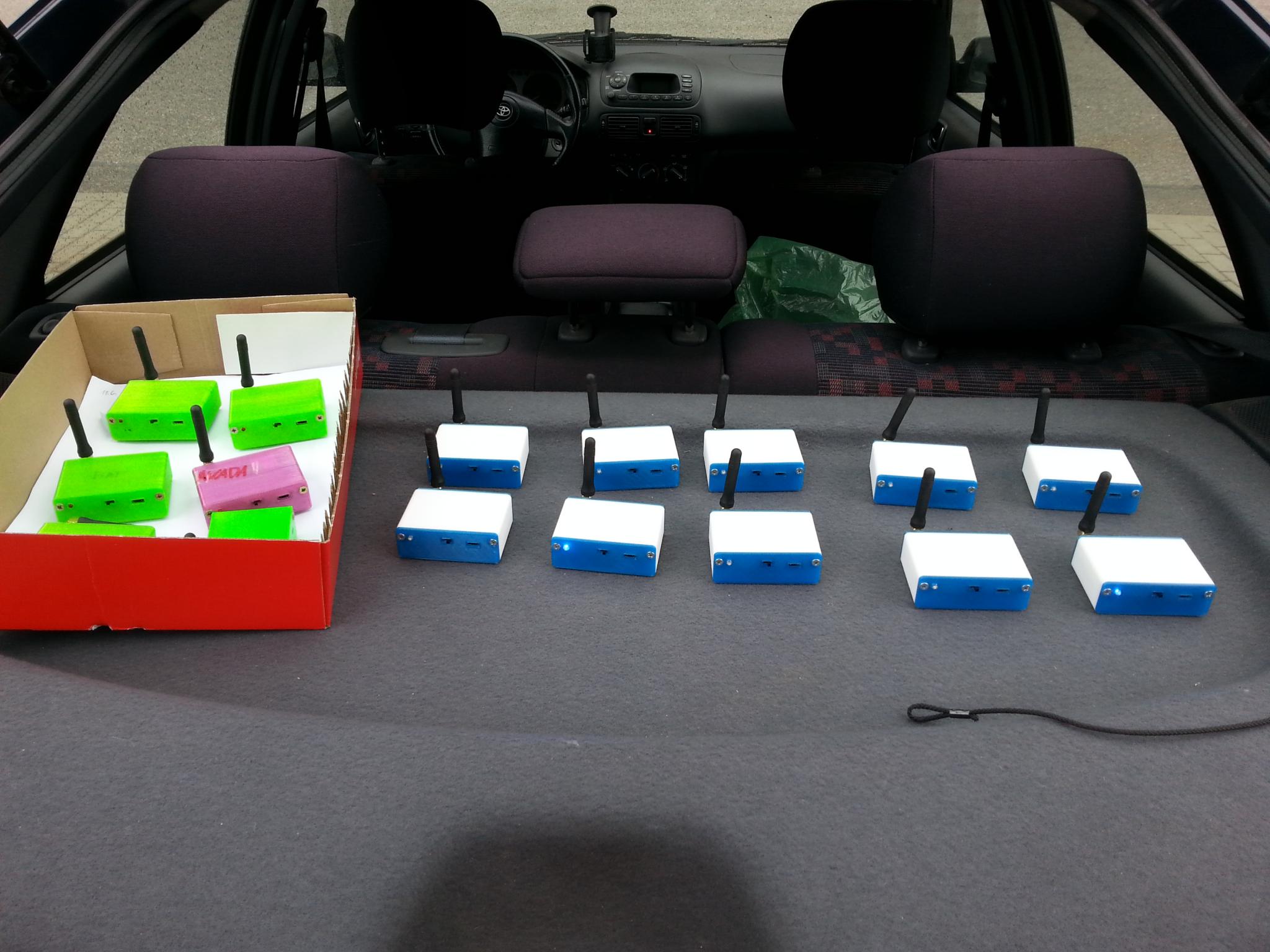
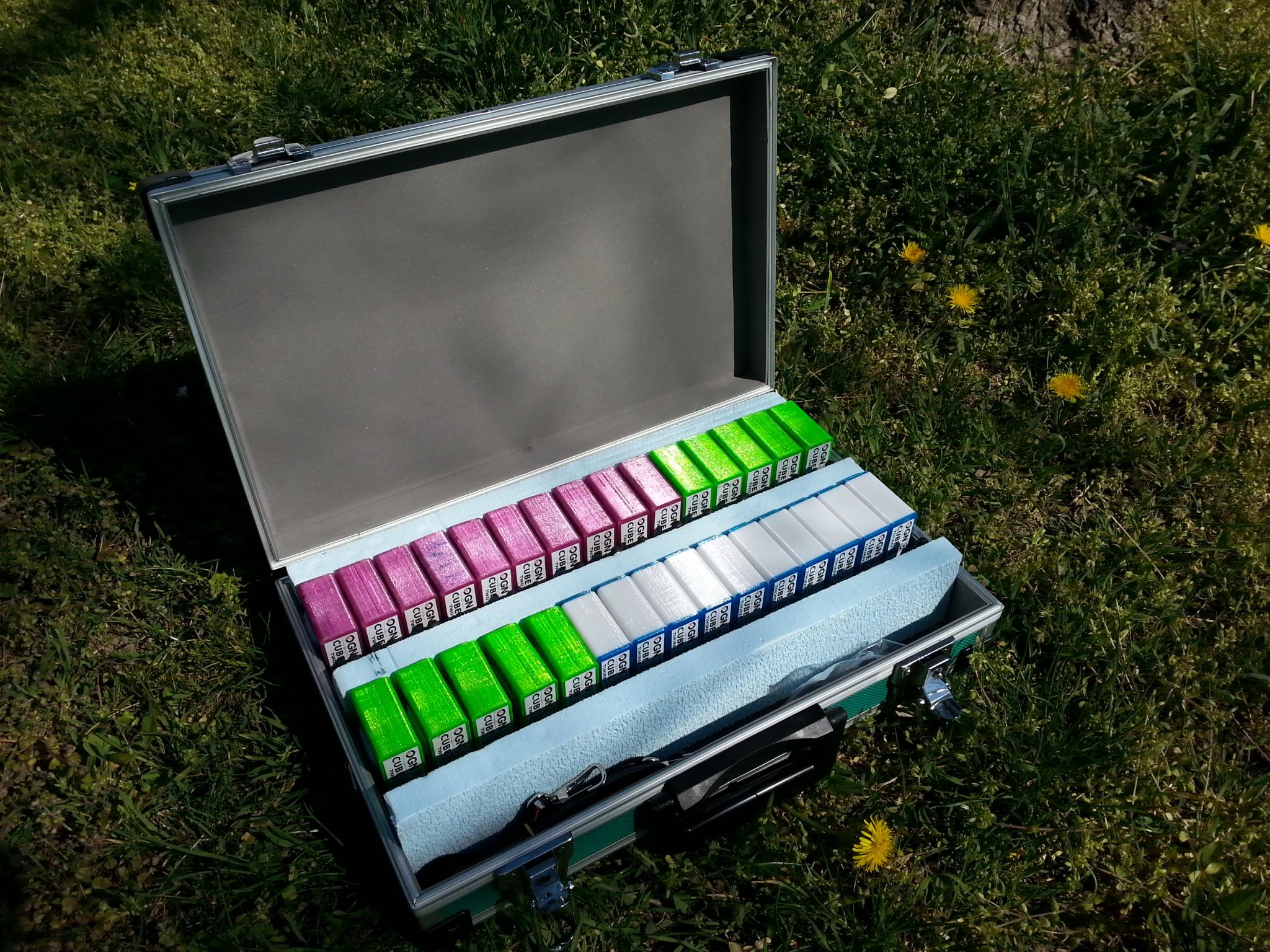
Long time no see, right? Over the last month I have been busy with some modifications on the PCB (oh snap!) as well as parts ordering, sorting, reordering missing ones, soldering and finally enclosure printing in order to finish a bit larger order of these little sweet boxes.

As thorough testing is part of the process I have been driving this load around the county for some time. I only wonder what the passersby might have been thinking.

All units passed with flying colours and hence could be nested into their new home.

Do you love it as much as I do? Great job, Ibisek, great job indeed! 🙂